• Please review our updated Terms and Rules here

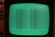
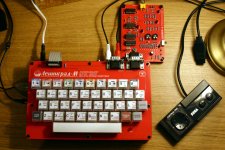
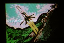
Replica of a Soviet ZX Spectrum clone

What software did you design those PCBs in?

You have me thinking about what a minimalistic Spectrum/CPM machine might look like... ( Without using ULAs ) - Maybe something Pandora-like.

Thanks for posting the journey - When you anticipate having a working model?

Also, why the lack of expansion port? I've noticed that isn't all that uncommon for some Spectrum clones?
 
What software did you design those PCBs in?
I used KiCad 8 for the first version, but now I'm using KiCad 9. I can definitely recommend it, it makes the design process way easier than I thought it'd be when I first got into PCB design.

It also lets you add custom fonts and logos to boards to make them look more interesting.
Thanks for posting the journey - When you anticipate having a working model?
I'll order the PCBs and components once I get paid at the end of this month. My JLCPCB orders usually take around 1-2 weeks to arrive.

I'm hopeful that the new version will work first time without any modifications; I've tested the new features in Logisim, so I'm fairly confident they'll function properly.
Also, why the lack of expansion port? I've noticed that isn't all that uncommon for some Spectrum clones?
Due to the hardware differences in the Leningrad design, I have doubts that accessories like the DivMMC would work properly with it. With some further improvements to I/O addressing, it might be possible to get an SD card interface working with it, but it'd probably have to be designed specifically for this computer.

I'll also admit that I'm still fairly new to hardware design - my first really ambitious hardware project was a simple 6502 computer I built based on the Ben Eater design about six months ago.
 
IMG_2212.JPGIMG_2210.JPG
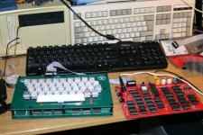
It works! I'm testing it here with the keyboard of the first Leningrad - the keyboard PCB for the new one is among the pile of parts on the right.
 
At last, the files are ready for download!

I have made one last small change. In Revision 1, the black level reference pulse was 24 pixels long; it turns out this is too short for it to be recognized by most TVs, so the black level was influenced by the border color.

In the new Revision 2, the black level pulse is now 32 pixels long. I've tested this fix on my Revision 1 system with a bodge wire, and it works perfectly now.

Keyboard PCB:
alex-j-lowry.github.io/download/lngrad-m/leningrad-m-kbd-allfiles.zip

System PCB (Revision 2):
alex-j-lowry.github.io/download/lngrad-m/leningrad-m-r2-allfiles.zip

System PCB (Revision 1 - provided for those who are interested to see the changes, but I don't recommend having this one produced):
alex-j-lowry.github.io/download/lngrad-m/leningrad-m-r1-allfiles.zip

Soon, I will write more documentation on the finished project on my website.
 
I've also made a PAL color encoder that connects to the main board based on the NIMF-4, a PAL encoder sold in Russia in the 90's.
IMG_2321_wb.JPGIMG-2240.jpg
You can download all the files for it here. It should be suitable for getting a PAL composite output from any system that outputs TTL-level RGB video signals and a separate sync signal. (so long as it has TV-compatible signal timing).

alex-j-lowry.github.io/download/nimf-4/nimf-4-r1-allfiles.zip

Some notes for those who want to build one of these:

It turns out Piher doesn't make 1.5kOhm potentiometers in the required form factor, but it works fine with 1kOhm potentiometers.

I also couldn't find a 5-25pF variable capacitor, but I found a 6.5-30pF one also works.
 
Last edited:
Back
Top