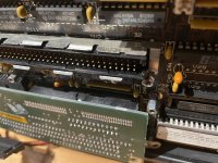
First time posting to the forum. I had a Compaq Portable III 386 back in the late 90s and wrote my undergraduate honours thesis in chemistry on it. Sadly I made the mistake of parting with it back in 2007 after not using it for several years. I'm now very keen to get one of these back up and running to use as a head node for our home computing as well as authoring some manuscripts on again for fun.
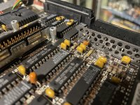
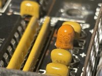
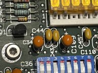
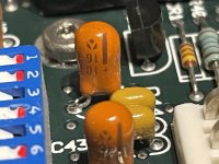
I have a Compaq Portable III 286 that's booting and has a Compact Flash to IDE card. It's too gutless to really do anything serious so I picked up a second Compaq Portable III off eBay for a very good price, with the only down side being that the seller said "Power supply is not attached"... actually they just meant there was no power cord. Plugging it in I could hear the fan engage for a fraction of a second and then everything stopped. Opening up the back and powering on again I can also see the red LED come on indicating a fault. Given how quickly everything stopped I suspected a short or something similar. Luckily I didn't have to investigate long and spotted the culprit as soon as I got the metal system board cover removed: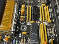
There's not much left of C47 and this is a little beyond my usual skill range - am I correctly identifying this as a tantalum capacitor? I think this would explain the power issue as I don't see any other obvious signs of capacitor problems. What the heck part to I order to replace this? Does anyone else with a Compaq Portable III know? There's not even enough left to read a part number off it!
There's signs I'm not the first one in the case as the screws were way over-tightened, a couple of the internal screws weren't put back but I can see signs of wear from when they were there. It's got a modem as well as the memory expansion board, except the board has no SIMMs at all (queue the hunt). Sadly it's missing the 32-bit interface board that bridges the memory expansion board and modem with the main board. Luckily I can salvage the interface board from my 286, as its interface board just sitting doing nothing as it has no additional expansion cards.
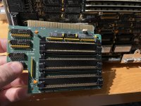
... it looks so empty!!
The main board has these SIMMS, but I'm not having any luck finding something equivalent on-line yet (except some site called Allegro.pl, but they don't quite look the same as mine):
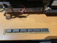
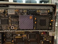
I also have this empty slot for another chip on my board (pic below) - does anyone know what this is and what component I should be looking for? Is this a co-processor, maybe?
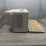
It also came with the expansion unit, which I've never had, but there's absolutely nothing in it except the board that connects to the expansion port.
Anyone have suggestions for things I should be considering for this?
I have a Gotek floppy emulator but I can't get my 286 Compaq Portable to recognize it regardless the jumper settings I use, but I'd ideally like to get this 386 setup with:
1. Booting off a Gotek or some other internal drive
2. USB memory support for transferring files if the Gotek floppy emulator isn't possible
3. Expand the memory up to the maximum possible
4. Internet access - telnet/ssh via Windows 3.11 would be sufficient. (I saw folks talking about a parallel port wi-fi adapter??)
5. Make use of all that space in the expansion unit - possibly a sound card, additional storage, or something else I haven't considered.
Any suggestions and info from the community here would be greatly appreciated - especially with identifying that capacitor
Thanks for any help you can lend!
~IM
I have a Compaq Portable III 286 that's booting and has a Compact Flash to IDE card. It's too gutless to really do anything serious so I picked up a second Compaq Portable III off eBay for a very good price, with the only down side being that the seller said "Power supply is not attached"... actually they just meant there was no power cord. Plugging it in I could hear the fan engage for a fraction of a second and then everything stopped. Opening up the back and powering on again I can also see the red LED come on indicating a fault. Given how quickly everything stopped I suspected a short or something similar. Luckily I didn't have to investigate long and spotted the culprit as soon as I got the metal system board cover removed:

There's not much left of C47 and this is a little beyond my usual skill range - am I correctly identifying this as a tantalum capacitor? I think this would explain the power issue as I don't see any other obvious signs of capacitor problems. What the heck part to I order to replace this? Does anyone else with a Compaq Portable III know? There's not even enough left to read a part number off it!
There's signs I'm not the first one in the case as the screws were way over-tightened, a couple of the internal screws weren't put back but I can see signs of wear from when they were there. It's got a modem as well as the memory expansion board, except the board has no SIMMs at all (queue the hunt). Sadly it's missing the 32-bit interface board that bridges the memory expansion board and modem with the main board. Luckily I can salvage the interface board from my 286, as its interface board just sitting doing nothing as it has no additional expansion cards.

... it looks so empty!!
The main board has these SIMMS, but I'm not having any luck finding something equivalent on-line yet (except some site called Allegro.pl, but they don't quite look the same as mine):

I also have this empty slot for another chip on my board (pic below) - does anyone know what this is and what component I should be looking for? Is this a co-processor, maybe?

It also came with the expansion unit, which I've never had, but there's absolutely nothing in it except the board that connects to the expansion port.

Anyone have suggestions for things I should be considering for this?
I have a Gotek floppy emulator but I can't get my 286 Compaq Portable to recognize it regardless the jumper settings I use, but I'd ideally like to get this 386 setup with:
1. Booting off a Gotek or some other internal drive
2. USB memory support for transferring files if the Gotek floppy emulator isn't possible
3. Expand the memory up to the maximum possible
4. Internet access - telnet/ssh via Windows 3.11 would be sufficient. (I saw folks talking about a parallel port wi-fi adapter??)
5. Make use of all that space in the expansion unit - possibly a sound card, additional storage, or something else I haven't considered.
Any suggestions and info from the community here would be greatly appreciated - especially with identifying that capacitor
Thanks for any help you can lend!
~IM

