• Please review our updated Terms and Rules here

Rusty Pet 2001 Project

mrlayance

New Member
Joined
Sep 19, 2022
Messages
2
Hello All,

Long time lurker, finally registered.

I acquired a rusty Pet 2001-32N and I need some help.

Replaced the fuse hold and got the Pet booting up. Now I have a garbled screen. I swapped around some RAM chips, same issue. Swapped around/removed the 6520's all with the same result.

Appears to have some sort of scientific addition.

What should I try next? Could this be causing issues?
 

Attachments

  • IMG_1716.jpg
    IMG_1716.jpg
    2 MB · Views: 26
  • IMG_1715.jpg
    IMG_1715.jpg
    1.9 MB · Views: 27
I'm not sure what the "scientific addition" is.

I'm only relatively recently familiar with these boards and I have successfully repaired two of them. There are a number of ways you could start the fault finding process.

Firstly it pays to have the Dynamic Pet schematics at hand, these are on Zimmers. I had them printed out to a paper folder with large fold out schematics to assist servicing.

The usual initial checks involve things like checking all the power supplies.

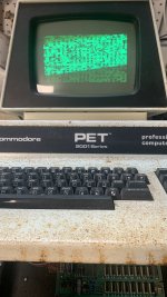
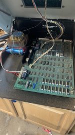
It is good that you have a display, even garbled, as at least a lot of the VDU's drive circuitry is working as is the VDU. And your 4116 DRAM and 2114 SRAM's are in sockets, this is very helpful.

One of the first things to check is that the 555 timer is sending out a proper reset signal. For example the screen you have is often seen momentarily after switch on before the boot to BASIC process takes place after a reset.

There are a number of CPU & address checks you can do involving a NOP generator that you will read about on the forum and various Romulan-Ramulating tools and Pettester ROMs to help diagnose trouble. Which others will show you how to use.

My approach was to confirm that the ROM's & RAM were all normal. To do this I created new ROM's from the TMS2532JL (and one 2716) and programming with the GQ-4x programmer. Also I had known good 4116's and 2114's IC's to fit. This allowed me to find the faulty ROM & RAM IC's via substituting the originals back in one at a time. After that I was able to focus on the remaining parts such as the PIA's and VIA and the TTL logic IC's. For testing, you only need to fit the ROW I DRAMS (it will boot with 16k of memory), this can help if some of the IC's in row J are defective and are corrupting the function of the Row I ram. It pays to stock up on spare RAM & ROM IC's, they come in very handy. Also the GQ-4x programmer is handy for reading the ROM's and comparing that to the Zimmers binary files. In one of my boards 3 of the ROMs were badly file damaged.

In general, if the DRAM Is defective in the lower 16k (or inhibited by faulty IC's in the upper 16k) you will have a black screen. If the CPU is not executing code (or proper code in ROM) then it won't boot to BASIC and you will have a garbled screen.


Ideally the tools you would have should include a meter & scope and at least a logic probe to start with, if no scope.
 
Last edited:
If you're burning ROMs, I have found this one to be essential in my fixing-my-PET journey. It replaces one of the ROMs and if the PET is working enough, it shows CRCs for the other ROM chips and tests the memory (and shows keyboard scans too). You may have further to go before this can be useful but I found it to be very helpful.

 
Last edited:
Welcome to VCFED.

Don't forget to add your location to your profile if you are able to.

There are plenty of threads under the Commodore section detailing how to troubleshoot this initial problem.

Power supplies first and then key signals around the CPU.

What test equipment do you have?

Dave
 
Scientific addition = some sort of interesting 'bodge board' with links attached to the voltage regulator heatsink in the top left-hand corner of the photograph of the internals.

Is it actually connected to anything? And, if so, what?

I find these 'odd things' interesting!

On closer inspection of the photograph I see there are a few flying leads connecting it to something on the PET board - and to a new external connector. Three possibilities come to mind off the top of my head:

1. A 'real' cassette interface.
2. A video interface.
3. A 'pseudo serial' interface for a printer or teletype.

I can only tell which one if I can get to see a close-up photograph (with lots of illumination) of both the little board and where it is connected to. The little board appears to have at least one transistor and a couple of resistors.

A fourth option I just thought of is an external audio output to an amplifier. This option is less likely though.

Dave
 
Last edited:
Thanks everyone for the reply’s. I don’t have any testing gear. Just a multi meter. I will have to do some more reading.
 
That's OK - we can do some testing with a multimeter... Is it an analogue or a digital multimeter? I am guessing a cheap digital multimeter?

You need to get your post level above 10 - otherwise the lag between you posting and your post appearing can get quite annoying for any meaningful testing...


Dave
 
Back
Top