• Please review our updated Terms and Rules here

RX01 Parts Needed

BitWiz

Experienced Member
Joined
Sep 7, 2021
Messages
435
Location
Glen Ellyn, Iil
I have acquired an RX01 dual drive set from a VAX780 (RX01W-VA). I am converting it to fit in my PDP-8 rack.

I removed the VAX cabinet frame.

I have the front panel but I need the following parts:

IMC PEWEE BOXER 80mm fan PWS2107FL-1000 cooling fan (this unit has an individual fan for each drive and one is bad.).
Dual Drive Front Plate (#74-12853-00). This is the black metal plate with the ridges in it that the front panel mounts to.
RX8E Controller

The drives came with a single diskette so I need some formatted diskettes also.

I don't know if the circuit boards are compatible with the RX8E Controller. The Read/Write Control Board is labeled 243A and the Floppy Disk Control Board is labeled 245A.

I don't have any other 8" floppy systems to format the disks in.

Thanks,

Mike
 
Curious about your progress on this. I’m in a similar situation with the RX01/RX02. My path has been like this…. don't have a full-up PDP-8/E, F, or M but have been able to find a good collection of PDP-8/E boards: M8330, M8310, M8300, M837, M8650 YA, M8320, and a programmers console. Still missing a chassis with power supplies. Designed and build my own 8-slot backplane (now wish it had one more slot). Sent Gerbers of Roland’s 32KW memory module to JLCPCB and built that up. I was concerned about trying to debug a PDP-8 system for the first time with core memory, and I knew debugging a 32KW static RAM would be easy. The stuff above seems to be functional now, and runs the MAINDECS images for the boards I have. Pushed MAINDECS images to the PDP-8/E system using RealTerm, my version of the ASR-33 paper tape reader but using RS-232 and running at 9600bps.

I want to bring up OS8, but kind of gave up on finding a real RX01 or RX02, so decided the next best thing was to build Roland Huisman’s M8357R and Roland’s 2-layer version of Don AK6DN’s RX02 Emulator. After ordering the RX02 Emulator boards from JLCPCB, I found a real RX02! Decided to build up the RX02 Emulator anyway, as that seemed like a safer approach to get the emulator running first with the M8357R and then swap in the RX02. I’m about to order the M8357R boards from JLCPCB.

When integrating the RX02 I was planning to start by setting it in RX01 mode, just because this avoids potential issues with creating a disk in the special RX02 format. However, I did recently purchase a box of 8” diskettes formatted for RX02. So the planned stages to bring up OS8 are, in chronological order:
1. RX02 Emulator, also will try operating it in RX01 mode.
2. RX02 drive operating in RX01 single-density mode
3. RX02 drive operating in RX02 double-density mode.

For creating the real RX01 floppy with OS8 image, I do have a Shugart SA801 plus an SA801-compatible second drive made by Siemens, attached to my old Z80-based CP/M system, still in a cabinet in the garage, hasn’t been booted in years. I hope the drives still work. The plan was to attach one of those 8" drives to an old PC running DOS and to perform the procedure to write the OS8 image, referenced in another thread here. Oh, I think I still have some blank but 3470-formatted diskettes to make an RX01 floppy.

So, the point of this long story is that I have extra RX02 Emulator PCBs and will have an extra M8357R PCB (minimum order is qty=5). I can send you one of each if you’re interested, can even send the RX02 emulator built with parts. I don’t need anything in return… except maybe I can send you a a single-density 3470 format floppy to write the OS8 image on it? I’ll probably get there eventually, but not certain of the status of my 8” floppy drives.

System in its present state...
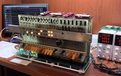
pdp-8e_running.jpg

RX02 Emulator. I have a bag of microSD card adapters from a prior project, but they have a 6-pin interface. The RX02 Emulator uses a SparkFun microSD adapter with 7 pins, and the pinout is different. The proto board resolves this. I'll probably purchase a SparkFun board, but just wanted to get the emulator running.
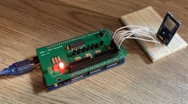
RX02_Emulator.jpg

1:1 size photo of a PDP-8/E front panel that I plan to mount to the rail on the programmer's console board, so it will look more like a real computer.
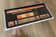
photo_of_fp_photo.jpg

RX02 unit is on the floor under my desk... didn't take a photo of it.
 
@gwiley

What a cool setup with that custom backplane!

You don't really need an 8 inch drive on a PC to write disk images to a floppy. To make real disks with only a PDP8 and a RX drive check out DUMPREST. You need disks which have been pre-formatted in the IBM standard. And if I'm right it can even be a CP/M disk, as long as it has the IBM standard. And now that I'm thinking about this, maybe it is a good idea to add the bootstraps to the bootloader for dumprest.

On several of my machines I have two RX controllers. One for the RX emulator the other for the real RX drive. So I have RXA0...RXA3 as floppy drives. (I modified the non system driver for RXA2 and RXA3) Even added serial disk as a non bootable device. The RX emulator is way faster. In that way I can use unmodified RK05 disk images.

But I guess everyone has its own way of setting up their system.
 
System in its present state...
View attachment 1238215
I like your homebrew PDP-8/e. Something like this would be an ideal debug platform for faulty boards.
You have even printed some nice looking switch toggles.
Congratulations and well done.
What is the small PCB to the left of the backplane board?
You might want to open-source and publish your backplane design.

Best regards
Tom Hunter
 
I have an old Shugart 800-2 that I am going to connect to a greaseweazle. This will allow me to format RX01 disks. Formatting RX02 disks will require a firmware change.

Any older system with an 8" drive that can format using IBM's 3740 standard format (77 tracks, 26 sectors per track, 128 bytes per sector) can format RX01 disks. Some of these would be CP/M, Flex, Radio Shack, CP/M-86.

As most of you know the RX01/RX02 cannot format disks (DEC's marketing wins over technology). Due to magnetic migration some disks might be unusable and reformatting may refresh the disk, at the loss of any data on the disk.

Products like the greatweazle are flux read/writers and might be able to recover the data on older disks (of any size).

Does anyone know an easy way to replace the felt pad on the backside of single sided drives?
 
@gwiley

What a cool setup with that custom backplane!
Thanks! There are a lot of connections to solder. I added slots incrementally as I got more vintage boards working. Your 32KW RAM was easy. It just worked right away with no issues :) I actually built two RAM boards. I notice the other one is sitting on top of the power supplies.
You don't really need an 8 inch drive on a PC to write disk images to a floppy. To make real disks with only a PDP8 and a RX drive check out DUMPREST. You need disks which have been pre-formatted in the IBM standard. And if I'm right it can even be a CP/M disk, as long as it has the IBM standard. And now that I'm thinking about this, maybe it is a good idea to add the bootstraps to the bootloader for dumprest.
Oh wow, I didn't know about DUMPREST. I'll definitely check it out. That'll make it easier to create the double density image too.
On several of my machines I have two RX controllers. One for the RX emulator the other for the real RX drive. So I have RXA0...RXA3 as floppy drives. (I modified the non system driver for RXA2 and RXA3) Even added serial disk as a non bootable device. The RX emulator is way faster. In that way I can use unmodified RK05 disk images.
Hey, thanks for this. I was actually planning to post this exact question, whether it's possible to have a system with two M8357s at different I/O addresses. I'm planning to build two of the M8357R so I can try this. Will start with them both attached to an RX02 Emulator.

BTW, having your designs available has been a HUGE help to bring up my system. Thanks much for that!
So far if have:
* built the 32KW RAM board
* built the RX02 Emulator
* about to build the M8357R
* have cloned the boot loader onto another board I designed with WiFi programmers console + RAM + boot loader
Never debugged the last one though, as I found a real programmer's console.
 
I like your homebrew PDP-8/e.
Thanks!
Something like this would be an ideal debug platform for faulty boards.
You have even printed some nice looking switch toggles.
I have to give credit to Vince at so-much-stuff.com for that. The switches are his design that I had 3D printed at JLCPCB. I also had printed Vince's Omnibus card handle. (There was some minor manipulation of the card handle stl file for JLC. I talked to Vince about it.)
Congratulations and well done.
Thanks.
What is the small PCB to the left of the backplane board?
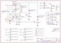
Very observant! So, this is kind of the opposite of a crowbar. The power supply rails are passed through this board which has super-low Rds-on mosfet switches. If the voltage rail exceeds a threshold then the switch opens. Contrast that to a crowbar that would trigger an SCR and short the supply. I'll eventually replace the lab supplies with switching power supplies for the +5 +15 -15 and +8 and was worried that a failure of a buck converter could send a very high voltage to my vintage pdp-8 boards. I actually had this failure happen recently on another project... cheap buck converter in my irrigation controller failed and sent 34 volts to an Arduino.

Another function of this board is that it detects low voltages and generates the Omnibus POWER OK signal. Three "okay" signals are anded from comparators monitoring +5 +15 and -15.

Here's one third of it...
Voltage Protector schematic p2.jpg
You might want to open-source and publish your backplane design.
I could do that. There's one mistake that needs to be fixed... accidentally shorted LINK L to GND. There are blue jumpers on the bottom side that aren't visible in the photo.
 
Formatting RX02 disks will require a firmware change.
If all you are wanting to do is format format them as RX02 you can format them as RX01 and then run RKFRMT on the PDP-8 to convert them to RX02. You can also use it to convert RX02 disks to RX01.

Does anyone know an easy way to replace the felt pad on the backside of single sided drives?
I went to a craft store and found some that looked reasonable, cut out some about the right size. Dug out the old pad and put in the new with a little glue. Seemed to work. Can't remember if I had to fiddle to get uniform pressure at the right spot. Is yours worn down so its flush with the holder?
 
Very observant! So, this is kind of the opposite of a crowbar. The power supply rails are passed through this board which has super-low Rds-on mosfet switches. If the voltage rail exceeds a threshold then the switch opens. Contrast that to a crowbar that would trigger an SCR and short the supply. I'll eventually replace the lab supplies with switching power supplies for the +5 +15 -15 and +8 and was worried that a failure of a buck converter could send a very high voltage to my vintage pdp-8 boards. I actually had this failure happen recently on another project... cheap buck converter in my irrigation controller failed and sent 34 volts to an Arduino.

Another function of this board is that it detects low voltages and generates the Omnibus POWER OK signal. Three "okay" signals are anded from comparators monitoring +5 +15 and -15.

Here's one third of it...
View attachment 1238259

I could do that. There's one mistake that needs to be fixed... accidentally shorted LINK L to GND. There are blue jumpers on the bottom side that aren't visible in the photo.

Thanks for the schematic and explanation.
While this circuit prevents over-voltage and reports under-voltage it does not shut down all rails when there is an over-voltage. This may cause damage to some boards.
A crowbar circuit would blow the fuse and all rails would turn off at the same time.

Best regards
Tom Hunter
 
While this circuit prevents over-voltage and reports under-voltage it does not shut down all rails when there is an over-voltage. This may cause damage to some boards.
A crowbar circuit would blow the fuse and all rails would turn off at the same time.
This is true, hadn't thought about that. Could add a circuit that OR's the over-voltage detection and shuts them all down. That function would need to be powered carefully. Something to say for the simple crowbar circuit that has low complexity and might be more reliable.
 
If you still need the RX0x mechanical parts, let me know. I think I have a drive that was complete but in really rough shape and not worth my time to restore.
 
I have acquired an RX01 dual drive set from a VAX780 (RX01W-VA). I am converting it to fit in my PDP-8 rack.

I removed the VAX cabinet frame.

I have the front panel but I need the following parts:

IMC PEWEE BOXER 80mm fan PWS2107FL-1000 cooling fan (this unit has an individual fan for each drive and one is bad.).
Dual Drive Front Plate (#74-12853-00). This is the black metal plate with the ridges in it that the front panel mounts to.
RX8E Controller

The drives came with a single diskette so I need some formatted diskettes also.

I don't know if the circuit boards are compatible with the RX8E Controller. The Read/Write Control Board is labeled 243A and the Floppy Disk Control Board is labeled 245A.

I don't have any other 8" floppy systems to format the disks in.

Thanks,

Mike
Curious what happened to the VAX 11/780 itself? Is it still around?

I'm embarking on a North American-wide search for one.... :)
 
Curious what happened to the VAX 11/780 itself? Is it still around?

I'm embarking on a North American-wide search for one.... :)
I noticed a listing for a /780 over in the classified section. I don't have anything larger than a /750 available.
 
I purchased the drive from the Rhode Island Computer Museum (IIRC)

I would post a message on the Vintage Computer Wanted Forum and the CCLIST saying you are looking for one. You never know what someone has in their basement or storage locker that is just looking for a good home.
 
it seems like a bit more than another wild project idea: though, how cool would it be to prototype an rx01 at thingiverse and treatstock? the alternative being to try and get your stereotypical diy floppy drive working on the first try...not. so what I saw was, someone here (roland?) was disassembling and restoring an rx01. so, the logic would be to ask them to post images of their parts next to a ruler. yes it would be cool to make .stl files, though I may not quite know how or have time, so it's still a thought. there may be schematics available for some of those DEC parts, yet there's no way to use them if you can't mount a drive head on a 3d prototype. so, perhaps let's see if anyone wants to measure or recreate the most rudimentary floppy drive anyone can think of. yes I am new here, my credentials are that I own a PC-XT, an AT-386, and others...about 20 pc systems. and I saw this bit of code missing at mame-dev: https://github.com/mamedev/mame/blob/master/src/mame/dec/decmate2.cpp#L989 and that I noticed this sale go down recently: https://www.ebay.com/itm/296102827554 (so literally save those pics while they're hot...) best regards, - Mdasoh Kyaeppd.
 
Back
Top