• Please review our updated Terms and Rules here

RX8E 74xx clone works

Roland Huisman

Veteran Member
Joined
Mar 24, 2011
Messages
1,470
Location
The Netherlands
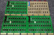
This week I got my RX8E 74xx clone boards, and with two hours of soldering the first one was ready.
After building the VC8E clone boards I've learned to test all chips before putting them into a board.
It is a bit of work but it can save a lot of debugging time... Especially when you are using old and
sometimes used chips like I do.
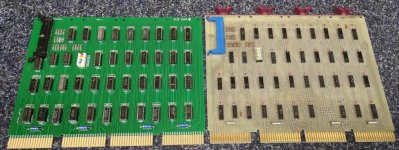
RX8E clone and original.jpg

After putting it in my 8M I ran the DIRXAC maindec and it passed it's test without a problem.

My own RX02 drive has some problems which I have to fix first. But tonight I got
another one and from that drive the left drive seems to work. So I put in some
OS/8 disks and see what happens. And it boots OS/8 :D:D:D
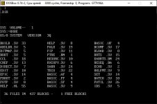
boot os8 rx8e.jpg

My plan is to put two of these controllers into both of my machines. One at 75 and one at 76.
At 75 I want to connect the RX02 emulator from Don North as primary device.
Just emulate an OS/8 boot disk and a diagnostics disk. I expect it to be quite fast because there
is no seek time. The second controller at 76 can be connected to a real RX01 or RX02 drive.
And in this way I can always use the machine as a stand alone machine...

I want to do a stress test before I release the files. But I think that it is a very nice and cheap
way of expanding your PDP8 machine... Just with standard 74xx logic chips... No DEC chips...

I'm really happy with the results so far, especially because I found a few errors in the RX8E schematics.
Having an original RX8E really helped me to filter these errors. It gives me a bit confidence to
make the TU60 controller. I will order these boards this week...

And yes, all files will be free to make your own boards if you want to. Give me a bit time
to make the partlists etc.

Regards, Roland
 
Nice work Roland! It's always good to see new OMNIBUS boards in the works; hopefully this should make the hobby more accessible too now that the original boards are getting expensive.
 
Thanks for the nice compliments! I've put some documents on GitHub
I will put the part list on a later moment. First I want to do some more testing.

For testing and primary boot device I want to use the nice RX02 emulator of Don North
since his emulator also passes the Maindec in combination with the RX8E.

The only thing which bothered me on the emulator project was the price of the four layer board.
At JLC the minimum amount is 5 boards. 5 boards are 28 Dollar which is just a bit to
high for free importing from China to the Netherlands. Customs and shipping
brings it to approx 53 Dollar.

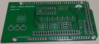
So I made a 2 layer version which is a lot cheaper. And because of that also no
customs to get the board here. So 5 of these boards are now $8.87 including shipment.

RX01 - RX02 emulator.jpg

I have no idea how this goes to the US or other countries. But if people like it
I can share these files as well. (I have to built the boards first to test them off course)

Regards, Roland
 
Yeah 2 layer should probably work just fine. I was just being lazy and wanted to try a cheap 4 layer project, so my $3 vs $6 per board cost was a non issue for me.
 
My RX8E M8357R clone card has been running the DIRXAC for a few hours on my RX02 drive and passed it with flying colours!
So I've added the component list at GitHub and in the meanwhile I've soldered two extra boards as well...

Three controllers.jpg

Now if you want to have a floppy controller you don't need Ebay any more. Just make your own...
All the files you need are here: https://github.com/Roland-Huisman/Digital_RX8E_M8357R
You can easily drag and drop the Gerber zipfile at a PCB manufacturer like JLCPCB

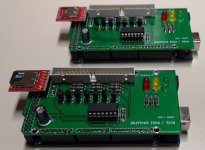
And my two layer version of Don's Emulator shield runs fine. I will put these files on GitHub as well...
RX02 Emulator.jpg

Since I have no RX02 disks I could emulate it trough Don's Emulator. Now I can confirm that the
bootstrap 10 (RX8 / RX01) and Bootstrap 11 (RX28 / RX02) on the M847 extended edition are both working and booting OS/8.

One of the five RX8E M8357R boards goes to Mattis. That leaves one spare which can go to another one person here.
I think $17.50 ex shipping is fair for the bare board. Getting a little of my costs back...

And please, if you are going to built a controller. Let me know! I love to have some feedback especially
because it does cost a lot of time, energy and a bit of money. Feedback gives motivation to go further.

In the meanwhile I've ordered the TA8E boards and a few others. To be continued...
I'm currently not working at new designs because I want to have the current projects done first.
These will be done in a few weeks.

And I will make an update of the original RX8E schematics because there are a few errors in it.

Regards, Roland
 
Last edited:
I've updated the original RX8e schematic. In the original file were these three errors:

Label "D3 MAINT (0) H" is wrong and must be "D3 MAINT (1) L" at pin 1 and 12 from E28 (7420).
Label "D2 XDR IOT L" is wrong and must be "D2 XFER IOT L" at E41 (7442).
And pin 13 of E28 is wrongly connected to pin 5 of E28. Pin 13 of E28 must be connected to pin 2 of U28.

I've updated the schematic and Al has put it on Bitsavers already:

http://www.bitsavers.org/pdf/dec/pdp8/omnibus/RX8-E_EngrDrws_Jun75_updated.pdf

Regards, Roland
 
This is a note presenting my experience in building, testing and using Roland Huisman’s RX8E 74xx clone controller board. My intent is to show the steps I took, as encouragement for others interested in the board to build it to see that it is a very doable project.

I have used the board to interface with my recently acquired RX02 floppy disk system. It could also be used with RX01 systems and based on Roland’s experience, with Don North’s RX02 emulator.

Credit goes to Roland for designing this board for PDP8 folks and presenting all the needed info on his Github site (https://github.com/Roland-Huisman).

Sourcing of Materials
Ordering the printed circuit board should be easy, using the gerber files on Roland’s Github site. I would have ordered the board from JLCPCB.COM as I have for Roland’s other boards, but he was kind enough to send me one.

There are a couple of options for ordering individual components. You will see two Bill of Materials (BOM) Excel files on Roland’s Github site in the folder “alternative component list”. I worked with Roland to find US sources for the components, and ended up with two versions:

RX8E M8357R Component list – 7400 series only – ver3.xlsx
RX8E M8357R Component list – max use of 74LS Chips – ver4.xlsx

The ‘7400 series only’ version stays true to the use of ‘original’ chips, while the ‘max use of 74LS Chips’ allows the use of somewhat more readily available and lower cost chips.

I used the ‘7400 series only’ version. The ‘max use of 74LS chips’ should be fine, as Roland has taken care to continue using 7400 chips in the more critical parts of the circuit.

You will see in the BOMs that sources are noted as Digikey (for most all components), Jameco (for components that I could not find at Digikey) and eBay (for chips that I could not find any other place). You may find the components from other sources – this is just what was convenient for me and worked…

Assembly Notes
Placement and soldering of the components went easily, using the BOM and the pdf file showing placement (see Roland’s Github site). I use sockets for all the ICs, which helps with replacements, but does add a little to the height of the board and cost (see notes in the BOM files).

The DIP switch (“Device Code Switch”) settings for addressing can be found a number of places online, including the “RX01/RX02 Pocket Service Guide” (Section 1.4.3). Normally this is set for 75.

A common practice with new boards is to file a 30 degree bevel on the sides of the edge connectors (eight places) to help with insertion.

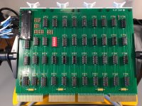
Huisman RX8E Board.jpg

Cable Options
There are a couple of options for cabling between the RX8E and RL01 or RL02 systems. One is the use of a BC05L-15 ribbon cable or equivalent (the ‘15’ is the length in feet, and other lengths are often available). Making one up should be doable.

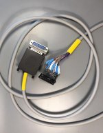
As I have a cabinet mounted RX02 with a DB25 connector on the back, I made up a DB25 to Berg cable. I checked and confirmed the connections to be consistent with Roland’s cabling info on the forum. If you can't fine Roland's cabling info, I can forward the spreadsheet I made up and used.

Here is a photo – not overly elegant, as it is made from a salvaged Berg connector, a screw terminal DB25 connector and a 90 degree adapter to save space at the rear of the cabinet:

Berg to DB25 RX02 Cable.jpg

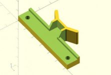
Board Handles
There are a number of 3D print DEC board handle models out there… Here is the one I have put together. It reflects the addition of an extended thickness to the standoff from the back of the board. This matches the standoff of vintage DEC handles that have spacers in-place and leads to a more centered alignment of the handles with the center of the board. No failures to-date.. Feel free to contact me if you would like the OpenSCAD and STL files (apologies, I don't see how to attach them to this reply).

PDP Card Handle - with integrated thick standoff - mng.jpg

Testing and Operation
The installed board successfully passed the DIRXAC.BIN diagnostics program – after some help from Roland with getting the correct program settings. Here is the screen capture:

SELECT PARAMATERS (INCLUDING DEVICE CODE)
SR= 0500 7000
TEST PARAMATERS: 7000
OD = 1 ID = 114 FIRST = 1 LAST = 32
SR= 7000

DIRXA-C PASS 0001I
WAITING^E
DIRXA-C PASS 0002I
WAITING^E
DIRXA-C PASS 0003I
WAITING^E
DIRXA-C PASS 0004I

Once connected to my RX02 system (which has only one disk running at present), it runs like a champ under OS/8 as RXA0:

Like my other posting on building Roland’s bootloader board, this write-up is a little sophomoric and unneeded by many in the PDP8 community, but I hope it helps folks that may be uncertain about taking this on to feel more confident that it is readily doable.
 
Hi Matt,

Thanks for your nice review!

A common practice with new boards is to file a 30 degree bevel on the sides of the edge connectors (eight places) to help with insertion.

Making that V-shape on the edge of the PCB was exactly that what the factory forgot to do with my first boards.
I complained about it and then I got another 5 boards which were done perfectly. :D I still have two of them.

Regards, Roland
 
Hi Don,

Thanks! That is a very nice PCB to have! I've downloaded the
Gerbers from there and ordered them at JLCPCB right away.

I've thought about using a printer switch box to switch between
my External RX02 and your Emulator. This makes it very easy to do :)
The DB25 is that a male or female on the board?

Regards, Roland

The RX02 box is a female DB25.

Adapter PCB has a STRAIGHT/VERTICAL male DB25 connector mounted on the BACK/solder side. NOT a right angle top side connector.
The IDE40 connector is a male box connector mounted on the TOP/component side.

This geometry allows the board to hang parallel to the backside of the box and not stick straight out.

Don
 
Last edited:
Back
Top