GearTechWolf
Experienced Member
First off, I know many don't find this to be a worthwhile project, preferring to build/buy an all-new or pre-rebuilt supply instead.
I respect that. It's a money-versus-time issue and most people have more money to put into this hobby than I currently do.
However, I have lots of time and enjoy nearly-lost-cause projects! So I purchased a second brick from a user on here.
I addition to recording the process of salvaging as many original component from within the epoxy as possible,
I will document difference between the two version of this supply that I currently own, the 13-'83 and the 3-'83.
Both are P.S.25 P/N251053-02, made in Singapore, marked with CSA and NLS, and "SHOCK HAZARD DO NOT OPEN" in English and French.
The 3-83 version is also UL-listed, marked 13J5 and "FOR USE WITH COMMODORE COMPUTER".
The 3-83 is rated at 117V 50/60 Hz 40VA input, and 5VDC 7.5W 9VAC 6.7VA output.
The 13-83 is rated at 117V 50/60 Hz 46W input, and 5VDC 8.5W 9VAC 9VA output.
The 3-83's markings are molded into the casing while the 13-83's marking are printed on the underside with the date on a metalized sticker and a label duplicating some information on the top.
The 3-83 has ribs running up both sides and across the top with a molded Commodore symbol in a blank square on top.
The 13-83 has a sticker on top with the C symbol, Commodore, Power supply, the input-output data, and the part number on it. Single row of narrow ribs along sides.
Of particular note is the slight difference in included electrical components within each unit. Both have the same count, but one component the other lacks.
The 3-83 has a 5A 250V fuse in-line with the 9VAC output and lacks the 2.2Uf 16V tantalum between pins 1 + 2* of the regulator. (but has the holes for it)
*(input and ground, respectively)
Now, for what you're all here for, the pictures!

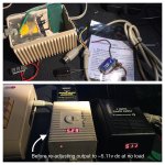
As found, after cracking the case open, a nice minty-green epoxy!

The bottom cover, slightly different in design from the one on the later case.

Close-up shot for wire-connections reference, and the fuse can be seen poking out of the epoxy here. (it didn't survive disassembly)


When I saw this line-voltage connection I though it had been burned out and was only hanging on by a couple strands!
(but I was wrong, that was the hollow space left in the jacket by the ground-wire, the line-wire is deeper. Can't explain the marks/discoloration though)

Here you can see where the three conductors of the line-cord were split, leading to my confusion with the one.

Input/output cords removed, fuse exposed*, and PCB cleaned off, de-soldered, removed.
*(scratched the glass, may have contributed to its destruction, but I doubt it would have survived excavation regardless)

Back of the embedded regulator. I partially backed the screw out by gripping the exposed threads, cut off the stub with a hacksaw, and drilled it out until the heat-sink was free.

The transformed in the 3-83 unit was wrapped with a single layer of masking-tape around the edges of the laminations, unlike the 13-83 unit.
Made it much easier to pull the epoxy away from it in large chunks!

Close-up of the embedded components exposed after removing the PCB. Four large legs are the two diodes, two thin legs are the .22uF 35V tantalum across the +5V output, three rectangular legs are the regulator, and the two resistors (100Ohm and 22Ohm) can be seen through air-bubble gaps in the epoxy. (no second, 2.2uF 16V, tantalum)
All component were nominally functional before tear-down.
On to page two!
I respect that. It's a money-versus-time issue and most people have more money to put into this hobby than I currently do.
However, I have lots of time and enjoy nearly-lost-cause projects! So I purchased a second brick from a user on here.
I addition to recording the process of salvaging as many original component from within the epoxy as possible,
I will document difference between the two version of this supply that I currently own, the 13-'83 and the 3-'83.
Both are P.S.25 P/N251053-02, made in Singapore, marked with CSA and NLS, and "SHOCK HAZARD DO NOT OPEN" in English and French.
The 3-83 version is also UL-listed, marked 13J5 and "FOR USE WITH COMMODORE COMPUTER".
The 3-83 is rated at 117V 50/60 Hz 40VA input, and 5VDC 7.5W 9VAC 6.7VA output.
The 13-83 is rated at 117V 50/60 Hz 46W input, and 5VDC 8.5W 9VAC 9VA output.
The 3-83's markings are molded into the casing while the 13-83's marking are printed on the underside with the date on a metalized sticker and a label duplicating some information on the top.
The 3-83 has ribs running up both sides and across the top with a molded Commodore symbol in a blank square on top.
The 13-83 has a sticker on top with the C symbol, Commodore, Power supply, the input-output data, and the part number on it. Single row of narrow ribs along sides.
Of particular note is the slight difference in included electrical components within each unit. Both have the same count, but one component the other lacks.
The 3-83 has a 5A 250V fuse in-line with the 9VAC output and lacks the 2.2Uf 16V tantalum between pins 1 + 2* of the regulator. (but has the holes for it)
*(input and ground, respectively)
Now, for what you're all here for, the pictures!
As found, after cracking the case open, a nice minty-green epoxy!
The bottom cover, slightly different in design from the one on the later case.
Close-up shot for wire-connections reference, and the fuse can be seen poking out of the epoxy here. (it didn't survive disassembly)
When I saw this line-voltage connection I though it had been burned out and was only hanging on by a couple strands!
(but I was wrong, that was the hollow space left in the jacket by the ground-wire, the line-wire is deeper. Can't explain the marks/discoloration though)
Here you can see where the three conductors of the line-cord were split, leading to my confusion with the one.
Input/output cords removed, fuse exposed*, and PCB cleaned off, de-soldered, removed.
*(scratched the glass, may have contributed to its destruction, but I doubt it would have survived excavation regardless)
Back of the embedded regulator. I partially backed the screw out by gripping the exposed threads, cut off the stub with a hacksaw, and drilled it out until the heat-sink was free.
The transformed in the 3-83 unit was wrapped with a single layer of masking-tape around the edges of the laminations, unlike the 13-83 unit.
Made it much easier to pull the epoxy away from it in large chunks!
Close-up of the embedded components exposed after removing the PCB. Four large legs are the two diodes, two thin legs are the .22uF 35V tantalum across the +5V output, three rectangular legs are the regulator, and the two resistors (100Ohm and 22Ohm) can be seen through air-bubble gaps in the epoxy. (no second, 2.2uF 16V, tantalum)
All component were nominally functional before tear-down.
On to page two!