• Please review our updated Terms and Rules here

SB11 PSU Schematic

eestes3

Member
Joined
May 5, 2022
Messages
39
Location
New Hampshire
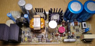
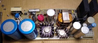
Hello, does anyone happen to have a schematic for the power supply in an SB11-EA shoebox system? Pops the fuse immediately, but I am going to see if it is fixable. The PSU board is double sided. I could sort it out eventually and generate a schematic, but it would be nice if someone has one. Haven't found one online yet.

Thanks.
 
Thanks, but no it isn't. The SB11 systems have a completely different PSU than what is in the TU58, even though the case matches. The SB11 PSUs have a FRU part # of 54-13343-00, but I can find nothing using that part #. Appreciate your time helping though.
 
Thank you for this. I need to study it a bit, but it may be what I am looking for or at least close. The board layout appears to be the same, but the SB11 only uses +5 and +12 vdc. Not sure about the other voltages this design produces. Maybe it is just a variant of the same design? The P2 plug for DC output looks the same, but the pinout is different. Thank you so much for taking the time to dig this up! Here is what the SB11 PSU looks like.
 

Attachments

  • sb11psu1.jpg
    sb11psu1.jpg
    1.8 MB · Views: 9
  • sb11psu2.jpg
    sb11psu2.jpg
    1.4 MB · Views: 9
This does appear to be it, possibly with some minor differences for the SB11 application. Thanks again Bitly!
Now how to attack this. This switching PSU is a bit beyond my knowledge and experience, but I will give it a try. Going to start with a recap, not knowing what else to do first. If I can get it to not insta-blow the fuse then I will have more to work with. Hoping none of the TO-3 transistors are bad. One is completely illegible (Q1) and cant find a match for Q2 (SC 9448 7921). The TO-3 switching rectifier (UES601) is legible, but cannot find a match for that either.

I know I could just throw a modern 1U PSU in here since there is no LTC or anything else beside +5vdc@5.6A and +12vdc@1.6A being supplied to the backplane, but I really want to save the original PSU if I can. Any advice or suggestions would be appreciated.
 
It looks quite like the VT100 supply. I never done a recap on the VT100 PSUs I have repaired. My experience is that the caps usually are in rather good shape. DEC often used epoxy sealed caps. Somewhat bad caps doesn't make it pop the fuse immediately. Rather check for bad semiconductors. Is Q1 the big TO3 switch transistor? I think that you can replace it with similar to what is in a VT100. NPN, High voltage switching. 2N6547 . All the diodes around the switch need to checked as well since they might have been causing the TO3 transistor to fail.. The VT100 has a fusible resistor in the base drive circuit. Perhaps it is the same here. Check the BLUE/Silver/Gold/Black/Brown resistor.
 
This is sound advice, thank you. Yes, Q1 is the big TO3 switch transistor. I will start with replacing Q1 and check all the surrounding diodes too. The big D17 TO3 switching rectifier (UES601) might also be suspect.
The VT100 psu is similar, but with notable differences. Taking a look at the attached description (thanks Bitly!) and partial schematic do you think the 2N6547 might be a reasonable replacement for Q1 in this PSU?
It does have a Blue/Silver/Gold/Black/Brown resistor. Not familiar with that color code. In circuit it shows 1.9 ohms across it. Assume I need to pull it out to properly test. Will try that later.
Thanks!
 

Attachments

  • H7833 PSU.pdf
    450.8 KB · Views: 5
Last edited:
partial layout if it helps. I think R11 may be the fused resistor you mentioned, based on the layout. You can see it in the first picture posted too.
 

Attachments

  • H7833 PSU3.pdf
    20.9 KB · Views: 4
In the VT100 there is exactly the same resistor. It is the R22, 1 Ohm 2 W FUSE according to the parts list.

This PSU is a lot less powerful so I think that the 2N6547 is a bit of an overkill at 15 amps max Ic. I think that something with the same voltage rating but a bit less Ic would work just fine. Actually I have seen BUY69A in several VT100 and it seems to work. So somethings like that should work fine.

If the output rectifier is short circuit I could guess that the PSU would shutdown because of overcurrent rather than poping the fuse. So in my opinion that one is probably ok.

I usually run the control logic separately from the rest to verify the operation of the switch-circuit. Just power the control-circuitry using a standard lab supply. Around 12V or so. Then you can feed the AC input from a variac and inslulation transformer and see how it behaves at very low voltages and currents. Less harm is done if there is something wrong.
 
Pulled Q1 and the D1 diode. It is bad. Hard to read the printing on it. It looks like 1j4m, but can find any reference for that. Well time to get to work. Some really good information and advice provided here. Thank you.
 
I should probably add that the diodes in the VT100 are named A114M or A114F depending on max reverse voltage. Perhaps this is what your diode also is named? Anyhow they are 1A fast recovery diodes. The M variety is 600 V max reverse voltage.
 
Back
Top