Though I guess that would go against S100 bus objectives of compatability.
Yes, playing games with the high address lines for I/O is likely a deal breaker for S100, or a lot of other Z80 computers with conventional decoding layouts...
Two out's is not a very high overhead for I/O mapped video - the BIOS calls would be the biggest delay per-character.
I mean, I guess it depends on how you're intending to use it. CP/M's BDOS function 9 takes a string, not a character at a time, so it would theoretically be an optimization (albeit an unnecessary one if you're comparing to serial I/O) to be able to do block moves, but... since this a "dumb" buffer you're probably going to need to run any string I/O through your terminal/ascii control code emulator before outputting it anyway. So I suppose being able to use the string functions would only really be useful for high-speed character graphics or whatever. (IE, literal "screen dumps".)
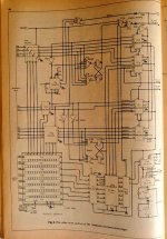
I have attached a video system that was published as part 5 of an article series in Wireless World in 1978.
FWIW, this appears to be the video system used by the NASCOM-1 computer. (See a bunch of manuals and full schematics for the computer at
the NASCOM home page.) This is an interesting design because it's basically a "dumbed down" TRS-80.
The TRS-80 has a 64x16 video display in 1K of memory *and it fits all 1K on the screen* because the horizontal timing counting chain is based on dividing the pixel clock into lines around 112 characters long with the horizontal margins and hsync pulse happening in the "7'th bit" area of the count, IE, not actually addressing the RAM, and using circuitry to reset the counters back to zero at this "odd" number. In other words, there are extra moving parts in order to "frame" all the memory into just the active area of the screen...
By contrast, the NASCOM display as depicted here is set up in the 64x16 memory grid, but it only displays 48x16 characters, "wasting" 16 characters per line, because it uses a slower pixel clock that divides the *entire horizontal line* into 64 positions, with some of the memory locations corresponding with the blanked margins and the hsync pulse area. That saves parts (you don't need to watch the video addresses and reset the counters at odd numbers, you can just let the h-count roll over) but, yeah, it wastes a quarter of the RAM and results in a kind of weird video memory map with holes in it.
This is actually related to what I meant when I said that using 128 bytes of memory to hold your 80 character lines could simplify your video memory addressing somewhat; if you want to "tightly pack" 80 character lines, which of course are not an even power of two wide, into a memory array, then you essentially need to implement a binary adder to walk through RAM in these 80 character chunks. If you don't mind wasting that RAM then, well, I think you could actually copy the "just let it roll over" horizontal counter idea of the NASCOM and just do it with a 7 bit counter instead of six bit. Doing some quick math... if you're using either NTSC or PAL (doesn't really matter, they have similar line rates) a 12mhz clock will work for 6 bit wide characters, you'll need a 16mhz pixel clock for 8 bit. (You would have to modify this counter chain somewhat to use 6 bit wide characters, though.)
Anyway, yeah, there are other wrinkles here; if you want more than 16 lines then there's some other changes that have to happen to this timing chain, and unless you modify how the hsync is generated you'll also inherit the gross memory map where your lines are going to need to start 12 or 16 characters from the start of each "line", but, eh, if you want to do completely discrete video in the fewest number of parts this is certainly an idea.
")