Upcoming Events:
| VCF West | Aug 01 - 02 2025, | CHM, Mountain View, CA |
| VCF Midwest | Sep 13 - 14 2025, | Schaumburg, IL |
| VCF Montreal | Jan 24 - 25, 2026, | RMC Saint Jean, Montreal, Canada |
| VCF SoCal | Feb 14 - 15, 2026, | Hotel Fera, Orange CA |
| VCF Southwest | May 29 - 31, 2026, | Westin Dallas Fort Worth Airport |
| VCF Southeast | June, 2026 | Atlanta, GA |
-
Please review our updated Terms and Rules here
You are using an out of date browser. It may not display this or other websites correctly.
You should upgrade or use an alternative browser.
You should upgrade or use an alternative browser.
Sinclair spectrum +2 gray model video issues (not transistor related, probably)
- Thread starter Divarin
- Start date
Divarin
Veteran Member
Well I think I'm getting closer.
I couldn't help be wonder why pin 5 seems to be connected to the yellow wire on the breakout cable if that's only supposed to be composite sync (not composite video) and that all of the diagrams show composite video on pin 1
so I decided to just discard the scart cable I bought and the scart breakout and just make a simple composite cable connected to pin 1 (and ground):
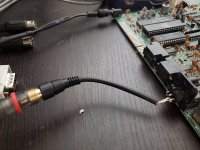
Now I get a picture which is the best I've seen so far but far from perfect:
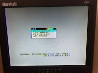
It has some ghosting. This could be due to two more transistors which need to be flipped or possibly I might need to add a 15 ohm resistor, or both.
I couldn't help be wonder why pin 5 seems to be connected to the yellow wire on the breakout cable if that's only supposed to be composite sync (not composite video) and that all of the diagrams show composite video on pin 1
so I decided to just discard the scart cable I bought and the scart breakout and just make a simple composite cable connected to pin 1 (and ground):

Now I get a picture which is the best I've seen so far but far from perfect:

It has some ghosting. This could be due to two more transistors which need to be flipped or possibly I might need to add a 15 ohm resistor, or both.
SiriusHardware
Veteran Member
That definitely looks like composite in your first picture where you have captured about 6 individual lines of video, each starting with a sync pulse. However the sync pulses are enormous in comparison to the size of the video brightness information so something may not be right.
Conventionally, composite video inputs have a fairly low terminating resistance of 75 ohms - the input of the scope is about a Megaohm. This means that the composite-out transistor on the Spectrum is not being given a proper emitter load when it is only connected to a scope, so to have a look at the composite-out properly, place a 68 ohm or 100 ohm resistor between the composite signal and ground, and then with the resistor in place, have another look at it on the scope.
Edit: I just caught your latest posts. That's good progress. To be honest Composite from a Spectrum was never the cleanest, that is why I always strove to use RGB instead. Try turning down the color control a little bit, it may reduce that color smearing.
Now that you know where to get composite from, you can try using RGB on Nautilus by feeding composite into its Csync input and of course RGB into the R, G, B inputs. It may be necessary to attenuate the RGB signals if the Spectrum is outputting digital levels on those lines.
Last edited:
Divarin
Veteran Member
Yeah this may be the best I can get with composite. I'll have to try rgb when I get those bnc to rca adapters. Too bad I can't connect rgb to the lynx monitor as that's kind of my "one monitor to rule them all" 
It does look a bit better with the monitor's brightness turned up and color turned down.
It does look a bit better with the monitor's brightness turned up and color turned down.
SiriusHardware
Veteran Member
It just seems to be a 'thing' that in Europe RGB was popular and supported by the almost universal SCART connector, whereas Stateside, YPbPr seems to have been the preferred direct color connection method. Over here we call that 'Component' video and while many TVs in Europe did / do have it, it was never used as widely as RGB was here. When the Xbox 360 launched here in the UK it came with a standard-definition 'AV' (Composite) video output cable and also another strange cable which looked like it might be an RGB output cable but defied all efforts to use it that way. Of course with the 360 having been produced primarily for the US market, it was supplied with a YPbPr 'Component' video cable, even over here.
SiriusHardware
Veteran Member
Just thinking, a little while ago I was involved in a thread regarding another retro computer project with composite video out. The guy who had made the PCB accidentally got the screen printing showing the orientation of the composite-output buffer transistor - same function as TR4 in this circuit - the wrong way around, so when he built his prototype he fitted the transistor the wrong way around. What was surprising was how relatively well it worked with the transistor in the wrong way around, the main effect was smearing and comet-tailing, not unlike what you were seeing there on your Spectrum / Monitor combination.
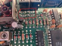
I'm saying this because I notice your TR4 is currently fitted the 'wrong' way around according to the screen printing which shows it should be fitted the other way around. Can I suggest you put it back the way it was originally and see what difference that makes to the quality of your composite picture?
If it doesn't look as though it has ever been disturbed, leave it as it is, but get hold of the pinout for the 2N3904, identify the 'E' (Emitter) lead and check that it is the 'E' lead which goes to the composite-out pin via a 75R resistor and link LK4. Also check that the 'C' (Collector) lead is connected to the 'Analog 12V' supply. If both of those cases are true then the transistor is in the right way around.
Last edited:
Divarin
Veteran Member
The reason it's reversed from the screen printing is, from all of the sources I've read, the reason they were installed backwards to begin with is due to mistakes on the screen printing, either that or they just ordered the wrong transistors. But that's a good idea I'll see if I have time today to put it back on the bench and see if it needs to be flipped back.
Divarin
Veteran Member
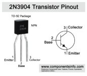
well based on this diagram:

and my measurements with a multimeter in continuity mode, and your post, it seems that the transistor *should* be installed the way it's depicted on the screen printing.
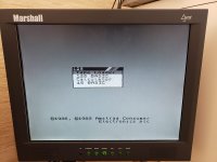
So I reversed it (putting it back to how it was from factory), but that was definitely a step in the wrong direction:
So I reversed it again, and it's back to how it was yesterday.
Strangely the various sites which talk about this transistor issue say it also is an issue with all of the other 3904's. I identified that TR4, 5, and 7 are 3904's so I tried reversing them as well but that didn't have any effect on the composite picture quality. I'll have to study the schematic more to see what those transistors are doing.

and my measurements with a multimeter in continuity mode, and your post, it seems that the transistor *should* be installed the way it's depicted on the screen printing.
So I reversed it (putting it back to how it was from factory), but that was definitely a step in the wrong direction:

So I reversed it again, and it's back to how it was yesterday.
Strangely the various sites which talk about this transistor issue say it also is an issue with all of the other 3904's. I identified that TR4, 5, and 7 are 3904's so I tried reversing them as well but that didn't have any effect on the composite picture quality. I'll have to study the schematic more to see what those transistors are doing.
Divarin
Veteran Member
Ha! well there's definitely a lot more work to do to actually use this thing. I tried recording a tape of a game just to see if I can load it. The tape drive seemed to work and the belts seemed to be in good shape but when I put a tape in it played for about 1 second then froze up. Oh well this thing's had a hard life I guess. At least I've managed to make some progress on it for the first time in a year. Thanks for helping me out.
I might see if I can just wire in external audio jacks for record/playback and use some kind of digital sound recorder (or a laptop).
I might see if I can just wire in external audio jacks for record/playback and use some kind of digital sound recorder (or a laptop).
SiriusHardware
Veteran Member
Regarding your tape problem, have the spools stopped going round when the unit is in PLAY mode? Common problem on those is drive belts - if they haven't moved for years they tend to harden into a fixed shape, they go brittle and then the next time the tape drive is operated the belt snaps. They are widely available, at least in Europe, possible over there as well.
Regarding the transistor orientation, there are things which don't add up. The collector of TR4 HAS to go to 12V, the emitter HAS to go to Composite-Out so if you are saying that the transistor has to be in the other way around to work that suggests that it is the pinout of the transistor itself which is internally reversed. I would be interested to know what is actually written on TR4, can you read it and post what you see or post a photo clearly showing the numbers on it?
What makes this interesting is that the 2N3904 is an American transistor which I would not expect to see used by default in a European design, more usually they would use something with a BC... or ZTX... prefix.
According to the diagram TR7 is involved with the IORQ circuit which is nothing directly to do with the video output circuit - turning it may actually break the operation of the machine until you turn it back, and TR5 is part of the buffer circuit for the Vsync signal (only) on its way to pin 5 on the monitor-out socket. As far as I know you are not using the Vsync output for anything so you won't notice any obvious effect if you swivel TR5. Try scoping the video output connector pin 5 (Vsync) - if TR5 is correctly oriented you should see a steady stream of short pulses coming out of that pin.
The only one you needed to worry about was TR4 which is the composite-out buffer transistor and you appear to have found the correct orientation for that one by experimentation.
SiriusHardware
Veteran Member
Just a quick note, I have been reading some of the articles which you have been referring to and at least one of them says this transistor orientation issue is confined to the issue 3 PCB. I was quite an early buyer, so mine is probably an earlier issue which may explain why mine has led a blameless life.
SiriusHardware
Veteran Member
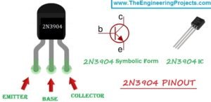
OK, I think I see the problem. I did find the 2N3904 pinout from your post #28, but I also found a load of others, of which just a random three are attached below.
Can you see? In all of these other 2N3904 pinout diagrams the Emitter and Collector are the other way around. You were a little bit unlucky to find that other one first. However this absolutely validates your finding that TR4 needed to be put in reversed, relative to the screen printing. The screen printing was obviously laid out with BCxxx devices in mind, they usually have the connections running the other way. It also suggests that TR5 and TR7 should probably be oriented in opposition to the screen printing, assuming that the screen printing was incorrectly laid for all three of those device positions.
Can you see? In all of these other 2N3904 pinout diagrams the Emitter and Collector are the other way around. You were a little bit unlucky to find that other one first. However this absolutely validates your finding that TR4 needed to be put in reversed, relative to the screen printing. The screen printing was obviously laid out with BCxxx devices in mind, they usually have the connections running the other way. It also suggests that TR5 and TR7 should probably be oriented in opposition to the screen printing, assuming that the screen printing was incorrectly laid for all three of those device positions.
Attachments
Divarin
Veteran Member
Oh wow how confusing, so the one diagram I managed to select is wrong.
Okay! Well that's one mystery solved.
The other two transistors I've already put back as they were (matching the screen printing) but haven't noticed any change. Of course I've not even come close to fully testing the computer as I can't load software at the moment. I just wrote some simple basic programs.
I suppose I should at least see if the sound is working. And take a look at the tape drive.
SiriusHardware
Veteran Member
I have a feeling the other two 2N3904s should also be mounted in opposition to the screen printing but I will look at the diagram this evening and suggest a couple of continuity checks (like you did on TR4) to determine which way TR5 and TR7 should really be inserted.
Divarin
Veteran Member
Based on the service manual PDF linked earlier:
Looks like TR5 goes to VSync, which might be an issue when I get around to hooking up RGB video.
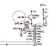
and TR7 ... goes to pin 40 of some chip and is labeled as IORQ. I can't tell which chip it is because it's right on the page fold.
but given the name, IORQ, maybe an interrupt line needed for certain types of I/O? Just taking a guess.
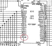
I think my desoldering/resoldering of TR7 managed to damage the pad on the underside of the board, the one going to the base of the transistor. Based on the schematic it looks like this pin should connect to pin 2 on the chip: PCF 1306P.
If I have time today I'm going to put it back on the bench and see if there's continuity there. If you still have yours on the bench would you mind checking to see if there is continuity between the base (center) pin of TR7 and pin 2 of PCF 1306P (IC10)? That way I'll know that if I don't have continuity that it's because I damaged the pad and I have to run a wire.
SiriusHardware
Veteran Member
I don't have mine to hand but I agree based on the diagram that IC10 pin 2 and the base of TR7 are both shown as being connected to 'A0' so yes, I would say you are right and those two points should be connected.
If you have damaged a pad or via take care, when you repair it, to make sure there is a connection between the track side pad and the component side pad if there are tracks going to the pad on both sides of the board. Damage to a pad on one side of a double sided PCB can often end up disconnecting the through - hole connection so that the top pad and bottom pad are no longer connected together. In the case of a 'simple part with no more than three legs you can 'fix that by soldering the pads to the component lead on both sides of the PCB so that the component leg itself remakes the lost through hole connection between the upper and lower pads.
If you have damaged a pad or via take care, when you repair it, to make sure there is a connection between the track side pad and the component side pad if there are tracks going to the pad on both sides of the board. Damage to a pad on one side of a double sided PCB can often end up disconnecting the through - hole connection so that the top pad and bottom pad are no longer connected together. In the case of a 'simple part with no more than three legs you can 'fix that by soldering the pads to the component lead on both sides of the PCB so that the component leg itself remakes the lost through hole connection between the upper and lower pads.
Attachments
Divarin
Veteran Member
strangely I don't see a trace on either side of the board, this isn't a multilayer board is it? Maybe I just need to break out some better magnification.
SiriusHardware
Veteran Member
I don't think it is multilayer, the layout diagram in the service manual does show a track leaving TR7 base, heading off in the general direction of TR8 and swerving around it. Without the board in front of me I can't really fathom out which track layer is top side and which is underside. An original copy of the service manual may well have shown the top side tracks and underside tracks in different colours but this one we are working from is a monochrome copy unfortunately.
Divarin
Veteran Member
Oh well anyway I was able to measure continuity so it looks like it's fine. Strangely tr7 and 5 seem to be connected correctly when oriented the same as the screen printing.
While looking for sometime else today I found some bnc to rca adaptors so I thought I'd try the rgb output on the nautilus monitor but couldn't get anything to show up. It could be that what I thought was rgb inputs is actually YPbPr. None of the port on the monitor are labeled.
The tape drive belt look fine but I think what I might do is make a wire to connect headphone/microphone jacks directly into the board so that tape files can be played in using some kind of digital audio device, maybe a laptop or an mp3 player. I'm betting there's a broken gear in the tape unit somewhere so I'll have to disassemble it at some point.
SiriusHardware
Veteran Member
Apparently adding an EAR (Audio input) socket is a fairly common mod for these but I don't know the details. I'm sure it wouldn't take long to find them.
Broken gears are not all that common in cassette mechanisms although there were certain models made by Philips where some of the gears were made with a semi transparent yellow / orange plastic which, decades later, has started to crumble like cheese. In fact they are sometimes nicknamed 'Cheese Gears'. I don't know who made the mechanism in the 'Amstrad Spectrums' but I would have thought it would be sourced in South East Asia.
What specifically is the cassette mechanism doing or not doing? When you put it into play, does the take-up spindle turn slowly? When in fast-forward, does the take-up spindle spin quickly? When in rewind, does the feed spindle spin quickly?
I've had success myself recently with loading Spectrum software into my original 48K Spectrum from the audio-out of a PC (see the tail end of Verault's current thread somewhere nearby). However, I have not modified my Grey +2 in this way (or indeed in any other way) as it is in complete, boxed original condition and I don't really want to do anything to 'spoil' it.
I fished out what I thought was my Spectrum +2 RGB->SCART lead last night - it is labelled as such - to have a look at the wiring for you only to find that I have at some point replaced the plug with a 13-way (Atari ST) plug. I guess I must have thought I had a problem with the original lead for the Atari and hurriedly modified the Spectrum lead to be an Atari to SCART lead. I don't even remember having done that.
On the plus side this means that I will have to remake the lead for the Spectrum and test it, in effect going through the same process as you, so we'll see how I get on with that.
Last edited:

