• Please review our updated Terms and Rules here

SOL-20 memory map

Thank you Walt. I'll bite and inquire what you are asking for a PCB plus 28C256 :-}.

Hi,

It would be nice to have a handful or people wanting a board and chip to make it worthwhile.

I figure $20 covers a blank board and a "Sol-20 Personality-32k" 27256, time & travel to/from USPS mailing in the USA.

I programmed six more 27256s ...


.
 
Thank you Walt. I'll bite and inquire what you are asking for a PCB plus 28C256 :-}.

Hi,

I wish there were a half dozen people wanting a board and a 27256 chip ... that would make the trip to the post office one trip worth the effort.

I figure $20 covers a blank board, a pre-programmed 27256 with the Sol-20 Personality 32k Multi-Choice Personalities, the driving to/from the post office and my time ... in the USA.


Send me an email with your shipping address and make a PayPal (friends & family) to: wperko athe brainless dotting org-anizm


.
 
Yes, the installation of the Micro Complex 80/64 card requires to remove 30 chips from the motherboard, as this board piggy back there. The only documentation I found about this card is there:


Yesterday, I went to my friend with my SOL and he burned me s SOLOS rom: the rom seems to boot correctly. I have a prompt, and I can use the EN and DUMP command! We changed the caps on the 64k memory expansion, tested all ICs and found that a 7425n chip is defective. Despite this chip being defective, I can obtain a positive memory test (under DPMON) on the two central memory bank, between 4000 and BFFF. The first bank (0000 3FFF) and the last bank (C000 FFFF) report errors. Removing the chip give errors on all banks. So, it's definitively related. Because the first bank from 0000 isn't working, loading .ent files fail. I'm looking now for this chip and hope that with a new one the whole memory board will work. On the pic you can see that I entered values in 0000 and that reading it back give another values, and on the other hand making the same on 4000 give back the correct values. There is a pic with the good memory test result too. This is where I am now. SOLOS boot, but for me it's still unclear if the .ent files can be executed correctly.

Small question: does the programs in .ent format have to access the video ram or the rom directly? I'm asking this, because I'm failing to understand how SOLOS can display something when the memory RAM is hidden by the Micro Complex board.

Hi,

I asked Lee Felstein about using a 64K RAM in the Sol-20 computer. Here's his response;

<quote>
I don’t think the Sol-20 blocks anything - you have to take care of that in the settings on the RAM board or you’ll have bus conflicts. Typically this means the board cannot respond to the C000 - CFFF block. The CC00 - CFFF block is used by the display and the C000 - CBFF is the onboard scratch RAM and the ROM personality module.

Lee
<end quote>


.
 
I've got something I didn't expect with the CRT screen I wanted to use to present the SOL-20: when I put the screen on the machine, or right next to it, the image suffers the electromagnetic field of the transformer and gets distorted into a wave. If I move the monitor 20cm away, it's fine. I tested a second monitor and got the same result. However, I've seen videos with similar monitors placed on SOL-20s without any problem. Have you ever seen this?

I've moved the 220V transformer away from 110V, so it's the SOL-20 transformer that generates the field.
 

Attachments

  • IMG_7985.jpeg
    IMG_7985.jpeg
    2.7 MB · Views: 7
Some VDU's are more sensitive to stray fields and some power transformers emit more magnetic radiation.

I'm not sure where you are located ? You mentioned 220 V so presumably you live in a line voltage area that has 220-250V line voltage (probably 50Hz) and are using a stepdown transformer ?

If this is the case there are a few reasons why the magnetic radiation from the SOL transformer could be a lot higher than normal.

The SOL's power transformer was designed for 60 Hz operation, is one factor.

Another is, 220/110V stepdown transformers often produce over half the voltage they are stepping down (to allow for full load conditions)

If your line frequency is 50 Hz, it is also equivalent (in terms of peak core flux) to running the transformer from 60/50 higher line voltage.

The maximum flux in Teslas, Tm in the core is:

Tm = V/4.44fNm^2

Where V is the voltage f is the frequency and N the number of turns and m^2 the cross sectional area of the core.

So lets say your line voltage was 220V (though likely it is higher), it could be 115v out of your stepdown transformer (not 110) and you have to allow x 60/50 in terms of the magnetic core's peak flux be equivalent to running your transformer off 138V , compared to the 60 cycle system. It will be worse if your line voltage is over 220, which they often are. In my area due to Solar inputs to the grid it can go up to 255V

With power transformers, the magnetic field radiation peaks up sharply over their rated input voltage, it is a non linear process as the core saturation is pushed too far up the B-H curve of the core material and there are peaks in the primary current waveform.

I found with my SOL it was better to run the input voltage in the region of 95 to 100v @ 50Hz. It had two benefits, one was no significant magnetic radiation from the transformer, but the other, this keeps the input to the 5V analog voltage regulators at around 8v, which minimizes the thermal dissipation in the SOL, especially if it is fully loaded with S-100 boards.Though I also added an additional cooling fan to blow more air across the S-100 boards.

If you power your SOL, via a variac, you can wind the input line voltage down. When it is in the region of 95 to 100V you will find that the regulator inputs are about 8V (it depends a little on how many boards it is loaded with). If you wind it lower, ripple appears in the 5V supply, no drama, all you see is ripple in the video. So one method to set the line voltage as low as it can be, is to wind the voltage down, until you see ripple in the video on the VDU screen, then wind it up and a little more after it goes away.

For my SOL, because of the large line voltage fluctuations on my area which are a pest (welcome to a less stable power grid due to solar inputs), I made a constant voltage machine, but you don't have to go this far. I used some vintage mil-spec OP amps and a Variac I had in my junk box:

www.worldphaco.com/uploads/THE_CONSTANT_VOLTAGE_MACHINE.pdf
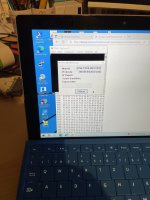
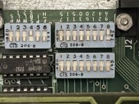
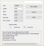
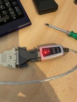
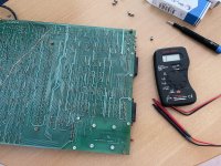
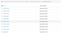
 
Last edited:
Thank you very much for these answers, as always, your work is well documented and precise, it's a pleasure. I'm going to try a different option, just for the pleasure of seeing if it works too: I'm going to use a double conversion, i.e. I'm going to use a 24V power supply to which I'll connect a 24V to 110V 60Hz car converter, so I'll have a 60Hz signal, and I'll be able to check that the magnetic field is dropping. Eventually, I'll probably use a voltage reduction like you.

Now I have another question (sorry :)) I'm trying to get my Micro Complex disk controller to work, which I understand is a clone of the Northstar controller. I'm using a VSG configured in 16 sectors (I'm not sure about that) and a TEC FB-504 floppy drive, which is apparently a 720k floppy drive. I'm trying to transfer a disk image with Tera Term by modem and with the PC2FLOP application.

when i press the "load" key under dpmon, the floppy drive lights up and tries to load from floppy, so i guess the controller is at the right address, but I'm not sure.

I'm stuck on the xterm transfer.

My questions are as follows:

- can a 720k drive be used, or do I absolutely have to have a 360k drive?

- Does the VSG have to be set to 16 sectors, or 10?

- how can I test if the addressing of the drive is correct?

- Does the tera term configuration need to be modified to transfer the disk file?

- to transfer the disk file, I use the "File>transfer>xmodem>send" menu, but the transfer doesn't start, it remains blocked. Is this the right procedure?
 

Attachments

  • IMG_8019.jpeg
    IMG_8019.jpeg
    2 MB · Views: 8
  • IMG_8022.jpeg
    IMG_8022.jpeg
    1.6 MB · Views: 9
  • IMG_8023.jpeg
    IMG_8023.jpeg
    2.8 MB · Views: 8
  • IMG_8024.jpeg
    IMG_8024.jpeg
    1.8 MB · Views: 10
The XMODEM transfer of the first group of tracks to write should work whether or not the subsequent disk write is going to work. Since the XMODEM transfer is not starting, there must be a serial port issue. Make sure the Sol-20 serial port is set for 8-bit word length and no parity. Selecting one stop bit provides a bit more speed. Of course, verify baud rate is the same on both sides (recommend 9600).

Mike D
 
thanks for your help. I think that my switches are correctly set, but I put a picture to show you what I selected.
Can you tell me if I'm using the right menu in tera term?
The standard transmission of .ent files work well, it's only when I select xmodem that nothing happen on the com port.

EDIT:
I tried with the menu "send file" instead, the file transfert is initiated, but nothing happens on the SOL-20 (see pic). But I really don't know what menu is the right one to use, xmodem or send file ?
 

Attachments

  • IMG_8026.jpeg
    IMG_8026.jpeg
    1.5 MB · Views: 10
  • IMG_8027.jpeg
    IMG_8027.jpeg
    2.5 MB · Views: 10
  • IMG_8028.jpeg
    IMG_8028.jpeg
    2.2 MB · Views: 10
Last edited:
Switch settings look correct. Verify with a meter that all off positions on the 6 position DIP switch actually read open. You‘ll want to use the XMODEM send option in TeraTerm, not the plain ”send->file” option.

On the “send file” picture, data is averaging 1.28KB/s, yet 9600 baud would max out at 960B/s. What baud rate is selected in TeraTerm? Are you using a real serial port (or USB ago serial adapter) or some sort of virtual COM port (e.g., TCP/IP, Bluetooth, etc.)

You’ll want to set the VSG for 10 sectors, but that has nothing to do with the XMODEM, issue.

You can use a 720K drive but the NorthStar CP/M will only use the first 35 tracks. Of course, the disks won’t interchange with a 48tpi drive.

MIke D
 
It seems like your serial link is working though there are some traps with it. The switch settings in the SOL hardware manual were incorrectly documented:

S4 2 & 3 said 7 bit was 2 =OFF & 3=ON, but it is 2=ON and 3=OFF, In other words they reversed the instructions for word length for 6 bits or 7 bits.

Also the Parity switching: SW4 switch 1 it said ON=EVEN OFF = ODD , but it is the other way around.

The other thing is, that if any of your current switch settings are closed, when they had been previously open over many decades, it is almost certain that the contacts in those pale blue CTS switches will have an intermittent connection.

I always used the 1200 baud setting to make sure everything could keep up. But, I never got around to transferring a disk image, only files so I cannot be of too much help.
 
Hi,

I found that at 9600 BAUD from TeraTerm ... on the <Setup> <Serial port> in the <Transmit Delay window> <10 msec/chr> and <100 msec/line> works well with both the "Send file" and <File Transfer> <XMODEM> ...


.
 

Attachments

  • TeraTerm SetUp2.jpg
    TeraTerm SetUp2.jpg
    41.2 KB · Views: 2
Do NOT use a delay for the XMODEM transfer. The XMODEM protocol has data throttling built in with its packet ACKnowledge requirement. Further, an XMODEM transfer is often binary data (as in this case in which a disk image is being transferred), so a delay per “line” is meaningless.

Mike D
 
@ everyone:
Many thanks for your help, I appreciate.

I carried out several checks: I dismantled the motherboard and checked that on block S4 only switch 4 was making contact and that switches 1, 2, 3, 5 and 6 were not making contact. This is indeed the case, I have a very good contact on switch 4. I did the same check on the other blocks, and everything's in order.

I don't quite understand this: "Switch settings look correct ", but then "Verify with a meter that all off positions on the 6 position DIP switch actually read open ".
Does this mean that switch 4 must also be open or not?

I've tested both variants (switch 4 open and closed), and it makes no difference.

I've also tested two other programs (extraputty and xmodem send), and got the same result: the transfer doesn't start. What I find strange is that when I launch the xmodem transfer, there isn't even an attempt at communication on the USB serial port adapter, no LED lights up.

In Teraterm (and in the other programs too) I've set the baud rate to 9600 bauds and deactivated the 100ms delay for xterm. With the 100ms delay, I can transfer .ent files without any problem. But I don't know if that's enough to validate that my serial link is 100% good, maybe xmodem uses other things? After that, I even tried at 2400 Bauds, and it's the same result (.ent files ok, nothing with modem).

I'm posting a photo of my serial adapter, could the problem be with it? I'm not sure where to look, I'd have to say....

as I have a Micro Complex disk controller and I read that it was a clone of the North Star disk controller, I used the version of PC2FLOP present in the "Northstar_dd_controller" directory, I don't think it has any influence on the start of the xmodem transfer on the serial port, but I'm only assuming.
 

Attachments

  • IMG_8030.jpeg
    IMG_8030.jpeg
    1.8 MB · Views: 4
  • IMG_8031.jpeg
    IMG_8031.jpeg
    4.2 MB · Views: 4
  • Capture d’écran 2023-08-21 à 10.13.09.png
    Capture d’écran 2023-08-21 à 10.13.09.png
    122.1 KB · Views: 3
  • Capture d’écran 2023-08-21 à 10.14.04.png
    Capture d’écran 2023-08-21 à 10.14.04.png
    119.9 KB · Views: 2
  • Capture d’écran 2023-08-21 à 10.14.50.png
    Capture d’écran 2023-08-21 à 10.14.50.png
    129.6 KB · Views: 4
Last edited:
Oh, it is a USB adapter. Probably fine.

Initially at least, I had trouble getting the simple serial port on my 20 year old vintage HP computer with an Athlon 64 CPU, running XP with Tera-Term to work with the SOL.

When you throw in a RS-232 to USB converter, it could possibly upset the apple cart, but it might not.

I heard there was a debacle over some serial to USB converter chips. Somebody cloned them, then the original manufacturers got annoyed, cut off their noses to spite their faces, and disabled their own chips to deactivate the clones.
(all sounds very Science fiction: "deactivating the Clones")
 
I ordered another SER to USB adapter, to be sure.

EDIT:
I noticed something strange on my SER connector in the SOL, there is a resistance soldered here, I don't see it on the schematic.... Can it be related?
 

Attachments

  • Capture d’écran 2023-08-21 à 16.59.02.png
    Capture d’écran 2023-08-21 à 16.59.02.png
    3.7 MB · Views: 2
Last edited:
Do NOT use a delay for the XMODEM transfer. The XMODEM protocol has data throttling built in with its packet ACKnowledge requirement. Further, an XMODEM transfer is often binary data (as in this case in which a disk image is being transferred), so a delay per “line” is meaningless.

Mike D

Hi,

Yes, XMODEM works well without the delays, but I find it's easier to just leave them set in TeraTerm because I'm still learning MBASIC and use the <File> <Send file> command a lot.

The delays don't upset XMODEM, just makes the transfer take a little longer, but the programs are so small I can wait 1-minute to complete.


.
 
@wperko:
When you transfert a disk, you simpiy choose the menu transfert/xmodem/send and select the file? No additional step that I'm maybe missing ?
 
Receiving .ent does not verify that transmission out of the Sol-20 serial port is working. XMODEM, however, requires the Sol-20 to transmit in order to receive. Use the SET command in SOLOS to set output to go to the serial port, then dump a range of memory and see if it properly transmits to your TeraTerm window ("SET O=1").

Mike D.
 
ok good idea. I just did a SET I=1 and typed in the terminal on the PC, what I type on the PC appear on the SOL-20 (logical, because the ENT files are transmitted). Then I did a SET O=1 and typed the command "dump 0000 0100", and the led on the USB to serial adapter don't blink at all. Looks that the communication work only in one way. Do you know what pin of the SOL-20 I have to check?
 
Hi,

The 25-PIN serial port should be very close to a standard from the day. Most of those PINs are still used today.

.
 

Attachments

  • DB25 DTE to DCE.jpg
    DB25 DTE to DCE.jpg
    28.8 KB · Views: 1
Back
Top