• Please review our updated Terms and Rules here

SOS! Tektronix 4006-1 terminal on the fritz right before the show!

stepleton

Veteran Member
Joined
Jan 1, 2020
Messages
535
Location
London, UK
Hi folks! I have five days (full of regular job) to repair a just-failed Tektronix 4006-1 vector graphics terminal before next weekend's Retro Computer Festival at the Centre for Computing History in Cambridge. Far enough off that we can try to fix it but soon enough for it to be stressful!

I haven't taken time to come up with theories yet --- I thought I'd write all the symptoms here first so that anyone who wants to help would have the maximum amount of time to join me in hypothesising. As soon as I finish writing this I'll... go to bed to be honest. But I will probably fall asleep reading the maintenance manual.

First, before I begin, voltages seem fine. With and without a load, all regulated voltages are within a few millivolts of their values. Display clearing (via the PAGE key and also by remote command) work fine. Incoming characters appear to be received and interpreted correctly: the terminal will enter and leave graphics mode on command, and even though only "squished" versions of text characters are shown on the display, these are the right height for the character the terminal is receiving (so _ yields . instead of | if you see what I mean).

I believe the problem may be a logic problem, but I'm not certain yet why the following symptoms emerge:

SYMPTOMS
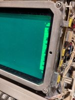
  1. Display is shifted far to the right, well outside of the usual display area. Text glyphs and the cursor are compressed into single "columns"; adjacent glyphs are smooshed next to each other. See this photo of what should ordinarily be a screen full of text. Graphics are similarly shunted over to the far right side of the screen.
  2. Strange keyboard (although it could be downstream of keyboard) behaviour: whenever a key is depressed, the terminal emits a stream of characters that are only sometimes related to the key. See mapping below. This effect varies depending on baud rate.
CHARACTER SEQUENCES REPEATED WHEN YOU PRESS A KEY

The table below attempts to show what the remote computer receives when different keys are pressed. Each character sequence associated with a key repeats at a rapid rate whenever the key is pressed: there is no classic "typematic" delay before repeating begins and repetition is frequent. So, pressing the G key yields a sequence of "WS/WS/WS/WS/W" etc. while T yields "DDDDDDDD" and so on.
Code:
Abbreviations for keys with long names:
AM = ALT MODE   PP = PAGE      LF = LINE FEED   SP = space bar
RR = RETURN     RO = RUB OUT   CC = COPY        BB = BREAK

Mapping:
1: ?!    2: "     3: #?    4: $     5: %#    6: &     7: '#?   8: (     9: )'    0: space :: *    -: =;     PP: (works)
AM: mk   Q: A_    W: GC_   E: US    R: B     T: D     Y: IG    U: CE    I: YW    O: _[W   P: @   LF: (note) RR: nothing?
A: Q/    S: C_    D: T     F: V     G: WS/   H: X     J: Z     K: YW[   L: \     ;: '+)  RO: omkgO/      CC,BB: nothing?
         Z: J     X: H     C: /S    V: F     B: R     N: ^     M: []    ,: <     .: >     /: 7?=;
                                            SP: 0

(note): LINE FEED sends an unprintable character

Using SHIFT with any key does not affect the behaviour. With CTRL:
  • These keys do the same as above: number keys, LF , . /
  • Y makes tabs
  • J makes a nonprintable character
  • RUB OUT produces a stream of omkg/ (note that O is missing from before)
  • Z gives line feeds
  • X is a backspace
DIFFERENCES TO THE ABOVE AT DIFFERENT BAUD RATES

The key behaviour shown was observed at 4800 BPS. For other rates:
  • 2400, 300, 150, 110: no characters reach the host
  • 1200: like 4800 BPS
  • 600: slightly different characters received, usually just one repeated instead of short repeated sequences
  • 75: like 600 BPS, though some incoming characters may be dropped
RESOURCES FOR THE DIAGNOSTICIAN

Tektronix 4006-1 service manual from 1977 --- with full schematics and short descriptions of system operation

Thanks for anyone's bright ideas! This terminal is meant to show dozens of cool vector images at the show; it would be a shame if it weren't working!
 
Thanks Dave, I was hoping you might chime in!

I won't be able to investigate further myself until mid-evening owing to work, but when that time comes, I have a two-channel 'scope and a 16-channel logic analyser. I'm not sure I have a clip for ordinary narrow DIPs, though.

One thing I forgot to mention is that when the failure occurred, the keyboard problems started first, with the display problems beginning a minute or two later.

The photo of what you get when you attempt to draw a screenful of text is attached.
 

Attachments

  • IMG_20231030_003906.jpg
    IMG_20231030_003906.jpg
    1.6 MB · Views: 17
My business trip this week may be cancelled - so I have a bit more time to think about your problem... I was supposed to be jumping into the hire car that is parked on my drive in 30 minutes and disappearing for the week. Anyhow, back to your problem...

I can't see (at the moment) how the keyboard and X deflection problems are interlinked - unless they are connected together by power supply or clock issues.

I assume you are measuring the power supply voltages directly on the power supply itself? Don't forget there are low-valued fusible resistors followed by smoothing capacitors on the various boards. If one of these have gone, you will have lost a partial supply to a board - and this could be the source of your X deflection problem?

I also keep coming back to the X deflection counter and X digital to analogue converter. Clearly the Y half is working - so the bulk supplies to the board appear to be fine.

Can I suggest checking out the X, XMOVE and XMAT signals? The XMAT signal is derived from the column counter of the character generator - I suspect this to be working OK. If X or XMOVE is not really changing much, I would concentrate on the X deflection counter and the associated digital to analogue converter resistor network and operational amplifiers.

If these signals appear to be OK, I would work my way through the display multiplexer and deflection amplifier board. There is some 'interesting' stuff on this board - a channel switch and geometry correction - that could have failed on the X side?

If we can get the X deflection sorted out - we may be able to resolve the keyboard issue.

Sorry I am not being much help...

I will think about that one next - but I have some real work that I must attend to now...

Dave
 
XMAT and YMAT are currents - so not too easy to directly measure.

X should be in the range +/- 7.75 Volts with a negative voltage being on the right-hand side of the screen.

Dave
 
I fired mine up. Its working well enough if you need I can check signals to compare to what your seeing. Screen is glitching occasionally and some keyboard keys are unhappy. Switch bounce on them will cause multiple characters but nothing like your seeing. If I have time later I'll look more. I do have bushiness trip starting Tuesday evening and have some stuff I need to get done before that.
 
The workday is over and while errands and a meal remain this evening, I'm eager to get started on the case.

POWER: I'm measuring voltages across the filter caps on the regulated lines (C166, C168, C172), so I don't think necessary rails are lost. I will check at the ICs later.

I was suspicious of power too since I had no other easy explanation for the near-simultaneous failures. But at the moment it doesn't seem to be what's wrong.

My first places to check will be clocks, the keyboard strobe line (if it looks strange then the keyboard almost certainly has a problem), and the X signal as described. I'll report back when I've done that.
 
Last edited:
Scoping things out: signs pointing to parallel failures in the keyboard and on the display board:

KEYBOARD: KSTRB indeed sending pulse chains that correspond to the frenzied typing. Something is wrong inside the keyboard unit.
CLOCKS: All look just fine.
X and Y: All values look quite sensible: smooth linear stepping through values ranging between +8V and -8V in keeping with the cursor positioning.

I have a pair of Tektronix 4051 computers: the 4051 display boards are quite similar to the 4006-1's display boards, which may make comparisons relatively straightforward.

My current theory about the cause is that the display board was in a fragile state yesterday: after a long day of slinging beams around, when the keyboard started fritzing out, it caused the program on the host computer to send a sequence of drawing commands (and lots of clearing) that finally wore out some component on the display board. Time to print more schematics and rotate the terminal 180 degrees on the bench...
 
Last edited:
For the record, this 4006-1 sports a vintage 672-0537-00 display board: first revision. Perhaps a blessing as there's less (no?) custom Tek silicon.

The 4006-1 service manual contains two sets of display board schematics; this is the second one.
 
I'm now suspicious of U777, the 5558 op amp in charge of amplifying the X position signal, yielding X AMP. You can see it in the [X SWITCH] section of the display multiplexer schematic, PDF page 78 of the service manual.

The X signal from the logic board enters the schematic just below the power supply inputs. At R772, the signal looks good, ranging as described above. On the other side of R772, the net going into the op amp, the signal ranges much less widely, between -4.4V and -6.6V (roughly). The amplified output ranges from -6.8V to -8.6V. (NB: Voltage measurements may not be too reliable: it's a bit hard to find a ground for my 'scope.)

We can contrast with the very similar Y circuit: inputs at R572 looking normal and then a much healthier swing of 4.3V to -3.6V on the other side going into U577 (the Y op amp). U577 output ranges from 9.4V to -5.8V. So a much more sensible behaviour.


Less likely possibilities in the neighbourhood:

The origin shifter circuit moves the screen around slightly in X and Y to avoid burn-in. These moves are really small and the resistor network between the binary counter that orders them prevents it from having much of an effect. Plus it affects both X and Y, and only our X is sick here.

The X AMPLIFIER (used for the screen-printing raster scan) section and Q674 can both affect the X AMP signal on the output side of the op amp, but an op amp is meant to have a very high input impedance, so I don't see how those downstream modifications could affect the U777 input.

I suspect instead that U777 is not so high-impedance anymore, and indeed is not much of an op amp anymore.


A next logical step would be to try and replace U777. I thought I had some 5558s but naturally I can't find them right now. I can probably source them quickly. Now, the quick-and-dirty method of replacement I have in mind is a bit medieval, so I'd love some double-checking of my diagnosis before I dive in: does the above make sense to people?

If so: because the display board is rather inconvenient to remove from the terminal, I'm thinking to cut out the 5558 DIP at the shoulders, bodge an improvised DIP-8 socket onto the pins left behind, and then stick a fresh 5558 into the socket. I can probably still solder some new legs onto the suspect 5558 if I want to evaluate the part later. But I think it should be clear why I'd like to be pretty confident in my reasoning before I reach for the side cutters! I can do a nicer repair later when I'm not under the same time pressure.

(ETA: What I have to hand are MC1458 op amps which may be a suitable replacement? I'll check datasheets. Pinouts match.)
(ETA again: The datasheet says that they're meant to be interchangeable with 5558s. Hooray!)
 
Last edited:
My 4006 has the later board so I can't measure the points you are measuring. Agree U777 seems most likely cause.

Did you measure the origin side of R773 to see which way its pulling the signal? Don't see any way is should be able to shift the signal negative so agree not likely. That's the only other spot that could pull the signal without a trace short on the board. You could cut pin 3 first and see if that fixes the input signal. May want to ground the IC side of the signal to avoid uncontrolled X. Using a resistor to ground would also show the same offset.

I agree your fix method should work fine. Slight change in parasitic but unlikely to matter.
 
I also agree. Sorry, a bit late to the party, but I have been at work where I am not allowed my phone!

Might be worth checking the power pins of U777 to make sure they are OK. I am sure you have, and they are...

Dave
 
Thanks both! It was indeed U777. Happy Halloween! 🎃

IMG_20231031_211612.jpg
(Vector artwork by Sean M. Puckett from plotterfiles.com)

Here's my quick and dirty socket bodge. Hopefully those smurf grenades back there will hold out through the weekend, and everything else, too!

IMG_20231031_211331.jpg

I'll settle for the terminal being a display-only prop at the show if it needs to be, but I'm still going to try to fix the keyboard next! The strobe generator circuit is a suspect...
 
Cute. Are you making available any new images?

I will have more photos like that in time, if that's what you mean! I have about 60 vector drawings I've prepared from various sources for the show. But for now: keyboard troubleshooting :)

Here's an odd question for 4006-1 owners: what is the oscillator frequency in your keyboard?

It takes some light disassembly to extract the keyboard (although you might not have to remove the main 4006-1 cover, I don't think), and then you have to power it up at the bench, so no worries if this is not something you wish to measure. But if you did, you can check pin 12 of Z1 or pin 13 of Z9 to get the frequency. Pin 14 of Z2 will also work if you aren't holding down any keys. On my keyboard it's about 280 KHz.

I ask because the strobe generator one-shot Z4 is meant to begin a pulse and keep it held as long as a key is depressed. Here's how it's supposed to work: when a key is down, the 74151 demultiplexer Z6 will pulse whenever the keyboard matrix scan encounters the depressed key. These pulses are supposed to be spaced no more broadly than 7ms: that's how long Z4 will hold its pulse whenever it receives the pulse from Z6 on pins 3-4. Repeating Z6 pulses should bridge Z4's pulses together into one long continuous pulse.

The problem for me is that my Z6 pulses seem to be a little longer than 7ms apart! Maybe they're more like 9ms. When you hold down a key, Z4 does not hold its pulse continually --- it seems like 9ms could be too long to wait.

I'm wondering if the keyboard has underclocked itself. Maybe the C2 value has drifted or Z1 has degraded somewhat. If your keyboard's clock is faster than 280 KHz, that would be pretty interesting!
 
I will have more photos like that in time, if that's what you mean!
Actually the files to generate them was what I was referring to. Always good to get more options to display. Pictures are also nice.

Here's an odd question for 4006-1 owners: what is the oscillator frequency in your keyboard?
I won't be able to make this measurement until late Thursday. Suspect that doesn't help you much.
 
Actually the files to generate them was what I was referring to.
I think I'm in good shape on that score. The plotter enthusiasts' community have made a lot of nice SVG files to work with; plus there's things on Wikimedia Commons etc. The conversion process then goes SVG->HPGL->Tek screen escape codes.

I won't be able to make this measurement until late Thursday. Suspect that doesn't help you much.
It might! If I'm still stuck by then, that leaves time for one last run to buy components on Friday evening. Hopefully by then I'll have worked out a solution, but if not, I'll say so here. Thanks very much!
 
Back
Top