• Please review our updated Terms and Rules here

Substitute LPT for monitor on IBM 5150

alejack12001

Experienced Member
Joined
Jul 26, 2020
Messages
428
Location
Fredericksburg, VA
I have IBM 5150 PC that I am standing up. I have had the motherboard for some 35 years and really never decided to build a system to support it, until now. I have acquired the support cards such as the CGA card, floppy controller and parallel/serial card. In addition, I have the 63.5 watt power supply and case plus two 360 KB full height floppy drives. Lastly, I have the Model F keyboard and multi sync monitor that supports CGA.

During a recent trial boot something was displayed on screen, Unfortunately there was a good bit of noise in the connection, which resulted in jitter and displayed error message that was unreadable. Okay, I have a shielded cable on on order for the video. I didn’t hear any beeps during POST; I did hear one after POST indicating POST passed. However, the floppy drive wasn’t engaged.

As a temporary substitute, I have a dot matrix printer that I can connect to the parallel (LPT) port. If a press print screen from the keyboard following turn on of the system would I see the error being displayed?
 
During a recent trial boot something was displayed on screen, Unfortunately there was a good bit of noise in the connection, which resulted in jitter and displayed error message that was unreadable. Okay, I have a shielded cable on on order for the video.
A lack of a shield is not going to result in an unreadable display. The shield is most likely there to reduce interference to other devices.

However, the floppy drive wasn’t engaged.
1. Verify that switch 1 on motherboard switch block SW1 is set to OFF (see [here]).
2. Verify cabling, termination, and configuration is per the 'Cable and Termination' section of [here].

As a temporary substitute, I have a dot matrix printer that I can connect to the parallel (LPT) port. If a press print screen from the keyboard following turn on of the system would I see the error being displayed?
Because DOS hasn't booted, the answer is no.

BTW. If DOS had booted, the following (from a book) suggests that the SHIFT key needs to be used also:
1670275754335.png
Because
 
A lack of a shield is not going to result in an unreadable display. The shield is most likely there to reduce interference to other devices.


1. Verify that switch 1 on motherboard switch block SW1 is set to OFF (see [here]).
2. Verify cabling, termination, and configuration is per the 'Cable and Termination' section of [here].


Because DOS hasn't booted, the answer is no.

BTW. If DOS had booted, the following (from a book) suggests that the SHIFT key needs to be used also:
View attachment 1249623
Because
First, thank you for responding. Regarding display problem: The monitor cable that I have came from eBay. It didn't have shielding even though as you say it's not needed. However, i think the cable is serial not a CGA cable for the monitor. I don't know if serial cables are interchangeable with CGA cables. If it is, then it should have worked. During POST, I saw what looked like 4 dashes across the screen in a moving direction from left to right. When something was displayed on screen, lines were overlapped similar to the dashes earlier. The CGA card is IBM and was recently acquired from a seller on eBay. Monitor allows me to adjust horiz and vert sizing, horiz shift and vert center. Monitor is good as I pulled it from another working machine. I tried a VGA card; but, the system objected during POST. One prolong beep followed by two short beeps after. With the VGA, I had switch 1 settings for 5 and 6 on and now with CGA, I have switch 1 setting 6 off (i.e., color 80x25).

I have switch 1 setting 1 already set to OFF, however, I think the floppy B may have a terminator on it and that is why the controller is not seeing floppy A where my DOS disk is located. The floppy controller looks like the one associated with minuszerdegrees, which shows block diagrams for the terminators on the 360KB floppies; but no pictures as to where the terminator is located on the drive. Do you have a picture of the terminator on the IBM full height 360KB floppy drive? This would be helpful.

Well, even if DOS had booted; I didn't know that the shift key worked in tandem with the PrtSc keys. Thank you for that information.
 
Regarding display problem: The monitor cable that I have came from eBay. It didn't have shielding even though as you say it's not needed. However, i think the cable is serial not a CGA cable for the monitor. I don't know if serial cables are interchangeable with CGA cables. If it is, then it should have worked. During POST, I saw what looked like 4 dashes across the screen in a moving direction from left to right. When something was displayed on screen, lines were overlapped similar to the dashes earlier. The CGA card is IBM and was recently acquired from a seller on eBay. Monitor allows me to adjust horiz and vert sizing, horiz shift and vert center. Monitor is good as I pulled it from another working machine.
'Serial' cables come in various configurations. Some are 'straight through', some are a form of 'null modem' configuration. Some are even missing wires because the wires are not required for the target application. I think that you should find the user manual for your monitor, and within that, look for a cable wiring diagram. Then go hunting the cable.

The CGA card is IBM and was recently acquired from a seller on eBay.
Presumably advertised as working.

Monitor is good as I pulled it from another working machine.
So, why are you not using the cable from that working configuration?

I tried a VGA card; but, the system objected during POST. One prolong beep followed by two short beeps after. With the VGA, I had switch 1 settings for 5 and 6 on ...
First, you will be aware from minuszerodegrees.net that for the IBM 5150, the 10/27/82 dated BIOS is required to support a VGA card.

With SW1-5 and SW1-6 both set to ON, {1 long beep then 2 short beeps} is expected to be heard if:

Possibility #1: User thinks that SW1-5 and SW1-6 are ON, but because of confusion between ON and OFF, SW1-5 and SW1-6 are actually OFF. See [here]. As a result, the motherboard's POST is looking for an MDA card, which it cannot find.

Possibility #2: The VGA card is what is generating the {1 long beep then 2 short beeps}. To see if that is the case, remove the VGA card. With no video card, and SW1-5 and SW1-6 both set to ON, {1 long beep then 2 short beeps} is not expected.

Possibility #3: User is confusing SW1 with SW2.

... however, I think the floppy B may have a terminator on it and that is why the controller is not seeing floppy A where my DOS disk is located. The floppy controller looks like the one associated with minuszerdegrees, which shows block diagrams for the terminators on the 360KB floppies; but no pictures as to where the terminator is located on the drive. Do you have a picture of the terminator on the IBM full height 360KB floppy drive? This would be helpful.
Because B: is optional, disconnect it for now if you think it is somehow causing interference.

IBM had at least two manufacturers make full-height floppy drives for the IBM 5150. If the one you have is the Tandon TM100-2 (or TM100-2A), then see the photo at [here]. If you have a different drive, you should be able to find a user manual for it online, or tell us what it is.
 
'Serial' cables come in various configurations. Some are 'straight through', some are a form of 'null modem' configuration. Some are even missing wires because the wires are not required for the target application. I think that you should find the user manual for your monitor, and within that, look for a cable wiring diagram. Then go hunting the cable.


Presumably advertised as working.


So, why are you not using the cable from that working configuration?


First, you will be aware from minuszerodegrees.net that for the IBM 5150, the 10/27/82 dated BIOS is required to support a VGA card.

With SW1-5 and SW1-6 both set to ON, {1 long beep then 2 short beeps} is expected to be heard if:

Possibility #1: User thinks that SW1-5 and SW1-6 are ON, but because of confusion between ON and OFF, SW1-5 and SW1-6 are actually OFF. See [here]. As a result, the motherboard's POST is looking for an MDA card, which it cannot find.

Possibility #2: The VGA card is what is generating the {1 long beep then 2 short beeps}. To see if that is the case, remove the VGA card. With no video card, and SW1-5 and SW1-6 both set to ON, {1 long beep then 2 short beeps} is not expected.

Possibility #3: User is confusing SW1 with SW2.


Because B: is optional, disconnect it for now if you think it is somehow causing interference.

IBM had at least two manufacturers make full-height floppy drives for the IBM 5150. If the one you have is the Tandon TM100-2 (or TM100-2A), then see the photo at [here]. If you have a different drive, you should be able to find a user manual for it online, or tell us what it is.
Thank you for the insight on the serial cables.

<Presumably advertised as working.> The seller of the CGA card had video, which showed the card to be fully operational. Now, I don't know if the video is recent or 5 years old. However, it did show video tests from checkit.

<So, why are you not using the cable from that working configuration?> The cable normally used with the monitor is VGA with an adapter to convert the VGA signals to accommodate the CGA (DB9) socket on the monitor. From my original post, I specified the connections acquired from the monitor manual. It appears the monitor can handle both CGA and VGA with the right cable. For the cable acquired from eBay, I'll have to confirm whether it is straight or missing wires.

<First, you will be aware from minuszerodegrees.net that for the IBM 5150, the 10/27/82 dated BIOS is required to support a VGA card.> BIOS on the IBM motherboard has dates of 1981, 1983 stamped on the BIOS ROM chips. The viddeo card is an 8-bit VGA card made by Western Digital under their Paradise brand version Plus. It has been used in other machines with success such as an old AT&T 6300 and IBM PC-XT 286. I belive the ROM date is 1987.

<
Possibility #1: User thinks that SW1-5 and SW1-6 are ON, but because of confusion between ON and OFF, SW1-5 and SW1-6 are actually OFF. See [here]. As a result, the motherboard's POST is looking for an MDA card, which it cannot find.

Possibility #2: The VGA card is what is generating the {1 long beep then 2 short beeps}. To see if that is the case, remove the VGA card. With no video card, and SW1-5 and SW1-6 both set to ON, {1 long beep then 2 short beeps} is not expected.

Possibility #3: User is confusing SW1 with SW2.>

So, let address these possibilities. Possibility #1 & 3. According to the 1981 service manual the switch locations, types and settings are spelled out in detail. Switch 1 and it's eight settings are for floppy use or not and whether the count of floppies are 0, 1, or more. Switch 1 settings 1, 7 and 8 address the floppy count. Switch 1 setting 2 is for co-processor, which is already present. Switch 1 settings 3 and 4 work in tandem with switch 2 for the amount of memory on the board, which is 256KB. So, switch 1 settings 3 and 4 are off. Switch 1 settings 5 and 6 are for the video. Your right the settings 5 and 6 are off as default for an MDA card. Equally the settings 5 and 6 being on state no video card or none. This is where minuszerodegrees state that an EGA or VGA card can be used provided that the card had it's own ROM. Otherwise the setting for 5 and 6 are off and on for CGA (40 by 25) and reversed with 5 on and 6 off for CGA (80 x 25). Right now my settings are the later 5 on and 6 off.

Possibility #2: I removed the VGA after the triggering of the beeps. Of course, I put in the CGA card. With the CGA inserted, the beeping stopped.

<IBM had at least two manufacturers make full-height floppy drives for the IBM 5150. If the one you have is the Tandon TM100-2 (or TM100-2A)> Well both of my 360 KB full height drives are Tandon TM100-2A. And with the picture you sent, the B drive did have the resistor while the A drive was missing the resistor. So I need to reverse the drives or connections.
 
Well both of my 360 KB full height drives are Tandon TM100-2A. And with the picture you sent, the B drive did have the resistor while the A drive was missing the resistor. So I need to reverse the drives or connections.
The requirement to have the terminator on whichever drive was attached to the end of the cable stems back to earlier days (e.g. minicomputers) where the cable used could be very long (e.g. controller in one cabinet and drives in another).

With the short cable used in the PC family, one can usually get away with the terminator being on either drive. But the manufacturers 'play safe' (why not) and specify the end drive. For that reason, I don't think the 'terminator on wrong drive' is the cause of the symptom ("the floppy drive wasn’t engaged" which I take as the A: drive's LED not turning on).

BIOS on the IBM motherboard has dates of 1981, 1983 stamped on the BIOS ROM chips.
According to the 1981 service manual the switch locations ...
Be aware that the 1981 manual applies to 'early' 5150's. For example, at that time, video cards with a BIOS ROM (e.g. EGA/VGA) did not exist.

Because your 5150 has the 10/27/82 dated motherboard BIOS (i.e. "1501476" will be printed on the BIOS ROM chip), the later manual is the better one to use. For example, it will reflect the fact that the SW2 switch settings changed in the move to the 10/27/82 dated BIOS.

Equally the settings 5 and 6 being on state no video card or none. This is where minuszerodegrees state that an EGA or VGA card can be used provided that the card had it's own ROM.
All EGA and VGA cards have a BIOS ROM.
For those cards, motherboard switches SW1-5 and SW1-6 are to be ON, and the 10/27/82 dated motherboard BIOS fitted.

( Step 20 at [here] details the video part of the POST of the 10/27/82 dated motherboard BIOS. )
 
Thank you for feedback and the corrections with regard to the operations manual. Yes, there are differences well noted.

Yes, I guess in the very early days of the floppy and hard drive the physical size and length of connections were important to the machine operations. In my case with this machine, I think I just need to move the terminating resistor to the twisted cable drive and verify the jumpers as shown on the minuszerodegress website. I had to modify a ribbon cable to accommodate the edge connector on the floppy controller card. These edge to edge ribbon cables are tough to find not alone to acquire.

I just checked the "1501476" on the motherboard and it's a Motorola chip with a copyright tag IBM and dated 1982. Below the title is XE and below that is 8410 A NM.

Your recommendation to use the 1984 Guide to Operations was the right choice. There are a number of differences with addressing the memory setting for Switch 2 especially for setting 6-8, which are off. As for the video, the settings appear to be the same for the CGA card. The offered link was very helpful in determining the sequence of steps profrmed by the 1501476 chip BIOS especially step 20 associated with the video card.
 
BTW. If DOS had booted, the following (from a book) suggests that the SHIFT key needs to be used also:
View attachment 1249623
Only if you have the original IBM PC/XT 83-key keyboard where Print Screen is shared with the numeric keyboard * key. Pressing the key alone will give you *. You need to press Shift in combination with it to get Print Screen.

Once DOS is loaded you can also press Ctrl+P to echo everything it displays on the screen to the printer. Press Ctrl+P again to stop the printer echo.
 
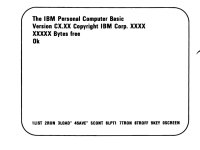
The first picture shown is from the IBM 1984 Guide to Operations when first starting with the IBM PC?
correct response.jpg
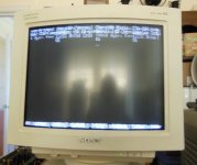
After getting the shielded CGA cable, the results are the same as with the original non shielded cable. Modem 7 you were right. The screen shown in the second attached picture its what I am seeing at 40 x 25. Actually, the settings for either 40 x 25 or 80 by 25 are the same. At this point to me the CGA card acquired appears to be defective. The odd thing is that if the monitor is off when the computer is started and turned on then I see the 3-4 columns as shown in the picture. If the monitor is on when the computer is started then I see twice as many columns. Also, the jitter seems there as well.

DSCN0017.jpg

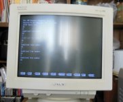
I removed the CGA card and set Switch 1 - 5&6 to “off” to accommodate the VGA card that I wrote about earlier. In the third picture, you can see the response from the card. This seems to match the first picture from the 1984 Guide to Operations. Notice that the total free bytes are 12252. What I am seeing on screen has me in a quandary as to what happened to the remaining RAM that is on the board. The board I have has 4164-20 TI chips soldered to the mother board as the first bank or bank 0 and three banks of IBM 2164-20 socket-ed chips, which of course makes 256 KB. Is this start up program that big to take up nearly all the RAM? Is this program the BASIC program written into the ROM chips? Each try that I entered from the numbered command line came back and stated undefined line number. So, how do I get this to jump from this program to the MSDOS Floppy drive? (Sorry about the glare in the monitor pictures.)

DSCN0018.jpg
 
Is this program the BASIC program written into the ROM chips?
Yes, known as Cassette BASIC.
For the IBM 5150, see [here].

Each try that I entered from the numbered command line came back and stated undefined line number.
By typing in only a number, you are telling BASIC that you want to delete that line of an existing program.
But you do not have a program present (either typed in, or loaded from cassette), i.e. the lines do not exist (are undefined).

If you want to simply execute a command (no line numbers required), an example is: print "apple"

A very simple program would be:
10 print "apple"
20 print "orange"
30 print "pear"


You would enter run to execute that.
If you then wanted to delete line 20, you would either enter 20 by itself, or use delete 20

Notice that the total free bytes are 12252. What I am seeing on screen has me in a quandary as to what happened to the remaining RAM that is on the board. The board I have has 4164-20 TI chips soldered to the mother board as the first bank or bank 0 and three banks of IBM 2164-20 socket-ed chips, which of course makes 256 KB. Is this start up program that big to take up nearly all the RAM?
Per the web page that I pointed you to, Cassette BASIC does not use all of the motherboard RAM.
Because your motherboard has 256 KB of RAM, and the version of Cassette BASIC is C1.1, then we expect Cassette BASIC to display "62940 Bytes free".

The fact that you are instead seeing "12252 Bytes free", suggests to me the following three possibilities:
1. Incorrect RAM related switch settings on motherboard, i.e. in switch banks SW1 and SW2.
2. Faulty switches in SW1 and/or SW2.
3. Faulty motherboard circuity that reads SW1 and SW2.

You have a 64KB-256KB type motherboard fitted with 256 KB of RAM. Per the information at [here], the required motherboard switch settings are:
SW1: 3=OFF, 4=OFF
SW2: 1=ON, 2=OFF, 3=OFF, 4=ON, 5=ON

If those are the setting you have set, then use Cassette BASIC per [here] to see if software is reading the switches okay.
 
I removed the CGA card and set Switch 1 - 5&6 to “off” to accommodate the VGA card that I wrote about earlier.
Per [here], that should be ON and ON for VGA.

OFF and OFF will still result in the VGA initialising itself (as you can see), but the problem is that the POST will believe that an MDA card is fitted, then issue '1 long beep then 2 short beeps' when it cannot find the MDA card.
 
The odd thing is that if the monitor is off when the computer is started and turned on then I see the 3-4 columns as shown in the picture. If the monitor is on when the computer is started then I see twice as many columns. Also, the jitter seems there as well.

Wait a second, that looks like a VGA monitor. How do you know it works with CGA cards? (The presence of a 9-pin connector on the back is not proof; early VGA monitors had both db9 and db15 analog connectors, and the db9 generally was analog RGB only, not TTL RGB like CGA cards put out. The only VGA monitor series I know of that does support TTL is the NEC Multisync series.)
 
The screen shown in the second attached picture ...
It appears that the monitor has synced to the 'vertical sync' signal (i.e. good vertical display), but not synced to the 'horizontal sync' signal.

It appears the monitor can handle both CGA and VGA with the right cable.
From your photos, the monitor is a Sony Multi Scan HG. From [here], the model number is CPD-1304S. Is that the model number that you have?

If so, there is a manual for the CPD-1304S online. In that manual, I see:
Vertical sync signal frequency: 55 - 110 Hz
Horizontal sync signal frequency: 28 - 57kHz

The sync signals for CGA are VERT=60Hz and HORIZONTAL=15.7kHz
And so a CPD-1304S will not do CGA.
 
So, how do I get this to jump from this program to the MSDOS Floppy drive?
Cassette BASIC does not support disk drives.

However, the floppy drive wasn’t engaged.
What should be happening is that when you power on the IBM 5150, at some point, per step 20 at [here], the POST will do a very crude test of the A: drive. During that crude test, which only lasts a few seconds, expected is:
1. The LED on the A: drive will be on; and
2. You will hear the A: drive's spindle turning; and
3. You will see the A: drive's head assembly move.

Are any of those three symptoms happening? Your "engaged" suggests none at all, but let's get the symptoms elaborated.

( Your post #3 and #5 above indicates that you are aware of the 3 floppy related switch settings on the motherboard. )

Yes, I guess in the very early days of the floppy and hard drive the physical size and length of connections were important to the machine operations. In my case with this machine, I think I just need to move the terminating resistor to the twisted cable drive and verify the jumpers as shown on the minuszerodegress website.
Presumably, you did what you indicated you were going to do.

I had to modify a ribbon cable to accommodate the edge connector on the floppy controller card. ...
Please elaborate on the modification. It could be the cause of the problem.
 
It appears that the monitor has synced to the 'vertical sync' signal (i.e. good vertical display), but not synced to the 'horizontal sync' signal.


From your photos, the monitor is a Sony Multi Scan HG. From [here], the model number is CPD-1304S. Is that the model number that you have?

If so, there is a manual for the CPD-1304S online. In that manual, I see:
Vertical sync signal frequency: 55 - 110 Hz
Horizontal sync signal frequency: 28 - 57kHz

The sync signals for CGA are VERT=60Hz and HORIZONTAL=15.7kHz
And so a CPD-1304S will not do CGA.
According to the monitor label, the monitor is a Sony CPD-1304 plain no S. The users manual that I have has the vertical sync frequency as 50 - 87 Hz and the horizontal sync frequency of 28 - 50kHz. In addition, the sync input is TTL level. So, what I am taking from the users manual for this monitor is that the monitor will take RGB/HV sync pulses and display them as if the monitor was an IBM 5153. Am I wrong about my assertion regarding this monitor. Also, I don't have a regular TTL monitor nor a composite signal monitor\TV otherwise I would be using that to receive whatever is being transmitted from the GCA card. One thing that may disquaiify the monitor is that the intensity signal from pin 6 of the CGA card is going to ground on the monitor. I don't know if this signal is having a profound impact on the monitor circuitry.

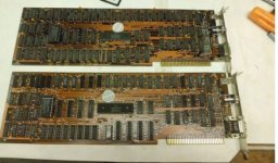
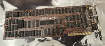
So, I have initiated are return for refund for the CGA card, however, I haven't shipped out the card as yet. The sellers photographs of the board that was sold don’t quite match the photographed boards displayed on the eBay posting. The first picture shows the boards that were from the sellers post. The second picture shows the received board; clearly the architecture is the same but the circular dot object shown in the sellers posted board is not the same as was received. In addition, the sellers technician is swearing that the card is good and was tested before shipment. What is your opinion on keeping it or not?

cards advertized.jpgIMG_4237.jpg

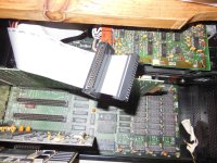
Regarding the ribbon cable. I just added an edge connector see third picture. You cannot find any of these type edge connectors so I just added the edge connector to connect to the floppy controller card. The twisted end is on the floppy drive itself. The B drive is shown in the picture while the A drive is on the opposite side.

DSCN0027.JPG
 
Yes, known as Cassette BASIC.
For the IBM 5150, see [here].


By typing in only a number, you are telling BASIC that you want to delete that line of an existing program.
But you do not have a program present (either typed in, or loaded from cassette), i.e. the lines do not exist (are undefined).

If you want to simply execute a command (no line numbers required), an example is: print "apple"

A very simple program would be:
10 print "apple"
20 print "orange"
30 print "pear"


You would enter run to execute that.
If you then wanted to delete line 20, you would either enter 20 by itself, or use delete 20


Per the web page that I pointed you to, Cassette BASIC does not use all of the motherboard RAM.
Because your motherboard has 256 KB of RAM, and the version of Cassette BASIC is C1.1, then we expect Cassette BASIC to display "62940 Bytes free".

The fact that you are instead seeing "12252 Bytes free", suggests to me the following three possibilities:
1. Incorrect RAM related switch settings on motherboard, i.e. in switch banks SW1 and SW2.
2. Faulty switches in SW1 and/or SW2.
3. Faulty motherboard circuity that reads SW1 and SW2.

You have a 64KB-256KB type motherboard fitted with 256 KB of RAM. Per the information at [here], the required motherboard switch settings are:
SW1: 3=OFF, 4=OFF
SW2: 1=ON, 2=OFF, 3=OFF, 4=ON, 5=ON

If those are the setting you have set, then use Cassette BASIC per [here] to see if software is reading the switches okay.
I got the memory description from the minuszerodegrees website and correctly adjusted the memory equal to what you posted, thank you for your feedback confirming the setting. I know there is a diagnostic floppy that would test the memory, but, the motherboard through the floppy controller has to reach out and shake hands with the floppy drives and neither of the two drives that I have illuminate the LED on the drive. So, the ROM is reverting to the built in cassette programs in the four ROMs on the motherboard. Chuck(G) helped me with the wired setup and I acquired a cassette that should work if I wire the connections correctly. I have acquired the manual on the 5150. Thank you for the insight on what the commands do.
 
According to the monitor label, the monitor is a Sony CPD-1304 plain no S. The users manual that I have has the vertical sync frequency as 50 - 87 Hz and the horizontal sync frequency of 28 - 50kHz. In addition, the sync input is TTL level. So, what I am taking from the users manual for this monitor is that the monitor will take RGB/HV sync pulses and display them as if the monitor was an IBM 5153. Am I wrong about my assertion regarding this monitor.
The manual here mentions only analog RGB:
Also other magazine articles shown on acrhive.org (I didn't read them all, just the first couple) only talk about VGA.

There was a previous model the CPD-1303 the does have options for TTL and analog, via a switch. I'm not sure if that's always the case, but the "multi-sync" monitors that I've owned that were capable of TTL and Analog all have a switch (or switches) to switch between those modes, they aren't automatic. Perhaps some monitors are cable of doing that? I don't know.
 
Have you tested the CGA card's composite output? Most TVs made in the past 25-30 years have a composite video input.
I have at least on flat screen monitor with red/white connectors for audio and red/blue/yellow for video. However, I am hampered by logistics as the machine and the TV are not easy to move.
 
Back
Top