• Please review our updated Terms and Rules here

Surface mount soldering help..

tblake05

Experienced Member
Joined
Aug 21, 2017
Messages
295
Location
Minnesota
Anyone comfortable replacing this chip?

It’s arcade PCB test equipment that isn’t being made anymore.... this version anyway.

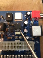
My inferior diagnostic skills have me believing that this chip is the fault. Mouser sells them on the cheap.

I’m just not experienced enough to trust myself to swap it. I can remove most of the through hole stuff before hand in the area if that would help.

What would you charge? I’ll cover shipping both ways. I just want it done right.

Thanks!

~Tim
 

Attachments

  • 7D4FE991-9BF7-4BAB-85B7-041B713669BC.jpeg
    7D4FE991-9BF7-4BAB-85B7-041B713669BC.jpeg
    1.6 MB · Views: 49
Not even a fine-pitch chip at that--you can do the replacement with a standard iron and some desoldering braid for cleanup. Several YT videos illustrating the process.
 
Looks like VERAULT has already positively responded; so just for general information ---

You do have a proper temperature controlled (not wattage - an actual thermostat controller) iron, preferably a digital one with a bonded tip-and-heater cartridge (such as T-15 style tips, or a TS100 or similar iron)? And you are using a large tip so that there is good heat transfer; and plenty of flux?

Proper heat control is essential to the process; you need to bring up all the pads to melting temperature, but not overshoot - an inadequate iron will heat a small area too hot (thus delaminating the copper from the board) while the rest of the pads are too cold.

Ditto on the Chip-Quik; if you aren't familiar with it, it's very low melting point solder that you apply to the pins you are trying to remove, and it stays molten long enough for you to remove the chip. Then you clean it off with desoldering braid and flux, and solder down the new chip with regular solder + flux. There's good videos of the process on YouTube.

Also VERY helpful is magnification of some sort - I use a stereo microscope, but you don't have to go to that expense; even just a desktop magnifying glass or "jewelers" magnifiers that you wear like a baseball cap help out tremendously when working with small parts.

I'd see if I could get ahold of some dead boards with similar surface-mount parts (e-waste?) and practice a bunch - like riding a bike, it's a skill and you develop it by trial & error.

:)
 
With a little practice can be easily removed with a standard iron,
but if you want to be safe just cut all the pins with a good flush
cutter and clean the pads adding some solder and flux.
 
I can't quite tell from the photo - zoomed in it looks like there might be some capacitor juice on the PCB???
 
I can't quite tell from the photo - zoomed in it looks like there might be some capacitor juice on the PCB???

Yes i saw that too and cleaned it off.... whether or not is was electrolyte or flux, the caps all measure good esr....
 
As far as soldering jobs go, this one is pretty easy.

There are two ways I might approach this removal: First I'd try just solder wicking, next I would try the low-temp alloy solder method.

Solder tip I use for pretty much everything is a Hakko T18-D12 chisel tip. This size tip would work just fine for this job. However if you're not comfortable with the larger tip, it's OK to swap tip to a smaller one after removal for the installation job.

Removal method 1: Solder wick (try first)
1) Use 60/40 solder to add a decent amount of solder to each pin. (gotta add solder in order to subtract solder...)
2) Apply flux to all pins. It is OK to be generous with the flux, as long as you clean clean clean it up at end of job.
3) Using #2 solder wick and clean solder tip, remove solder from each pin. Watch an example video if you're unsure how this works.
4) After all solder has been removed, try to push the IC off of the board. If we're lucky, she should pop off the pads. Use moderate force, but be careful not to use too much force and lifting the pads as a result!
If the IC is not popping off of the pads using moderate force, proceed to removal method 2.

Removal method 2: Low-temperature alloy solder
Get yourself a Chipquik SMD removal kit (Digikey 315-REMKIT-ND). It contains a special low-temperature solder alloy that remains molten for a longer period of time.
The idea is to apply the special low-temp solder to each pin, then use your solder tip to melt the solder on all of the pins simultaneously; the solder will remain molten long enough for you to just slide the IC of off the pads.
NOTE: Use as little amount of the low-temp alloy solder as you can. You can easily create a disaster with this stuff, as it can spread and adhere to everything else around the area you're working.
1) Apply flux to all pins.
2) Apply small amount of low-temp alloy solder to each pin.
3) Drag solder tip across all pins on each side to melt all of the solder on each pin.
4) Gently push the IC of off the pads while the solder is still molten.
5) Use solder wick to remove ALL of the low-temp. solder when done.
6) Inspect area to ensure no low-temp solder got away from the job area, remove as needed
7) Clean away all flux

New IC installation:
1) Apply regular 60/40 solder to 1 pad only, usually pin 1. For this part of the process, the rosin core of the solder should contain a sufficient amount of flux, such that no additional flux is needed. If your solder doesn't have rosin core, you'll probably need to add flux.
2) Grab IC with tweezers and set IC onto pad, line up the pins with the pads.
3) Use the solder iron to tack on the 1 pin you applied solder to.
4) Adjust position of IC as needed while IC is tacked on with just 1 pin.
5) Solder remaining pins.
6) Clean away all flux.

Let me know if you run into any issues.
 
Last edited:
Yes i saw that too and cleaned it off.... whether or not is was electrolyte or flux, the caps all measure good esr....

Check the rubber plugs in the bottom, especially around the legs coming out. If you see any wetness or crusty brown resin looking stuff, the seal failed on the cap and it needs to be replaced.

ESR is one thing, but you need to also check capacitance. If the measured capacitance is out of the +/- 20% tolerance, it's bad and needs to be changed.
 
I've mentioned this before, but for removal, I powder some of an ingot of Cerrobend 158, pack the powder in around the package pins and use a PAR-38 incandescent spot to heat the area from the reverse side of the PCB. The package will eventually slide right off when the board temperature has reached about 100C, without bothering any of the surrounding components. Cleanup of both the package and the PCB with a toothbrush and the heat from the PAR38. Discard the removed solder as hazmat, as the Cerrobend does contain some cadmium.

This really works well in tight spaces when dealing with fine-pitch TQFP ICs.

I know that some don't like this because of health concerns because of potential inhalation of cadmium oxide furmes, but the oxide doesn't form under 320C. The tiny amount of cadmium probably doesn't matter in any case, when viewed from the standpoint of tin-lead solder. At any rate, I'm too old for it to matter. :(
 
As for the cost, it would depend on various factors such as the complexity of the replacement process, the type of chip, and the time required to complete the task. You may want to research local repair shops or technicians and compare their rates to determine a reasonable cost for the service.
 
Proper heat control is essential to the process; you need to bring up all the pads to melting temperature, but not overshoot - an inadequate iron will heat a small area too hot (thus delaminating the copper from the board) while the rest of the pads are too cold.
Question about the temperature. What temperature do you normally use as a starting point for leaded solder? And do you use the same temperature for through-hole and SMD components?
 
Question about the temperature. What temperature do you normally use as a starting point for leaded solder? And do you use the same temperature for through-hole and SMD components?

What melting point the solder melts at entirely depends on the alloy. Generic 60/40 leaded solder melts between 360-460F, but the problem is that the circuit board wicks heat away from the iron, making it a lot harder to melt solder. If you're working on an area with large power planes, it can be even more difficult, often requiring the board to be pre-heated to avoid damaging components with excess heat.

Through hole components can require a lot more heat than SMD because of the leads going through the board, where multiple layers of traces can sink heat away. I'd recommend preheating the area to 200F to make it easier to remove components. The only exception are capacitors, you don't want to directly heat them, because they'll boil internally and may explode.
 
I have a full lab and the equipment to do the job.
I'm a retired design EE.

Can do the work for $40, just insure three things:
1. Place the board and new spare part in an anti-static bag while you are grounded, (or bare footfoot in cotton clothes),
2. Bubble-pack the heck out of it then place in a good/sturdy cardboard box.
3. Enclose a prepaid return

Hope that helps
 
Hey guys, actually was able to replace the chip myself. @hard_fault gave me the confidence to try SMD soldering again. Worked like a dream. Yep, didn't fix it. My poor diagnostic skills again!

I poked around a while with it and realized I wasn't getting a clock signal. It was short to ground. Weird, as I could have swore the old chip had a clock signal to it that matched the working one.

Anyway, I desoldered the crystal oscillator, ran the board with it out, and it had the same issue. Tested the oscillator on the bench with my 5v power supply and it worked fine?? Odd. So I soldered in a socket and put it back on and poof. Running good!

Not sure if maybe the crystal was shorted to ground or what, but it's been running fine for a week.. Only time will tell.

Thanks though guys!
Thanks for the update. I have a thought for you to consider: Crystals too often do not do well in sockets over time due to a number of potential issues... pin oxidation, dis-similar metals, continuity gaps, temperature changes, humidity fluctuations, particulate contamination of one nature of another, capacitive coupling, added inductance, ad nausium. These issues can appear singly or in concert, transient or permanent, be mild or worsen with time, so think about it. I strongly recommend you actually solder the xtal in (with MINIMAL solder time per pin) and BTW: it is okay to "stand off" the device from the PCB a little (just in case there is a short waiting to happen) - you can even use 1-3 layers of trimmed computer paper to do so. Myself, I often use a trimmed-to-size popsicle stick (flat) to do the job, depending on the xtal type, and generally remove it when finished.
 
I did notice the crystal fit loosely into the socket so was planning on soldering it directly to be more permanent. Though was hoping to actually replace it with a new one next time I place a digikey order.
 
Back
Top