• Please review our updated Terms and Rules here

Tandy 1500HD/2810/3810HD Laptop 26-Pin FPC Floppy Drive Ribbon Cable

Paralel

Experienced Member
Joined
Mar 27, 2013
Messages
333
Location
SW Quadrant of Michigan
Does anyone know if the 26 connector FPC floppy drive ribbon cable pinout for the Tandy 1500HD/2810/3810HD laptops is known? Or if it is a common standard?

I've come across a number of 34-pin + floppy power connector to 26 connector FPC floppy drive cable adapters and want to find out if that would allow me to adapt a 34-pin servo type floppy to use with the 1500HD I have.

The floppy drive in question is a Matsushita EME-263MG. The 26 connector FPC cable is permanently attached to the drive (seems kinda like a stupid design given how prone FPC cable are to various problems...). I searched quite a bit but came up with practically nothing about the drive or its pinout.

Any info is appreciated.
 
Last edited:
I imagine the connector and pinout is similar to the one used in the Tandy 1100/1110HD which is documented (I made a couple of home-made adapters for those models a few years back, before I became better at fixing the original drives). I've seen and wondered about those adapters you are referencing, but I've not had time yet to determine if a) the pinout is the same in the floppy drives used in the 1500HD (and their Panasonic cousins) or b) if the adapters would work.

If I get to it first I will let you know, but if you or someone else finds out, it would help if they posted back as well.

Well, I ordered one, so I'll report back with my experience once it gets here.
 
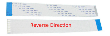
To follow up on this, the 34 pin to 26 conductor FFC adapters have the 26 pin interface upside down compared to the Matsushita (Panasonic) drives in the Tandy laptops, as a result the pinout is reversed. As such, you need to use a "reverse" FFC cable to interface between the adapter and the Tandy laptop floppy controller. A "reverse" FFC cable has the conductor interfaces on each end of the cable on opposite sides. Here is an image for anyone that is having a hard time picturing that:

ReverseFFC.png

Of course, as far as I know, no one has ever created a reverse FFC 1.25 mm to 1.00 mm cable. There is a forward FFC 1.25 mm to 1.00 mm cable that can be purchased, but you would have the end of the FFC cable interfacing with the floppy adapter in reverse. You could still use it, but you'd need to use an FFC extension board with a second reverse cable in order to swap the direction of the conductors on the FFC cable to match the pinout of the floppy adapter.
 
That is unfortunate. Perhaps the adapter was engineered to work with the synthesizers that use similar Matsushita drives (and seem to provide more business in this area) and that is why they are "reversed", and don't quite work, out of the box (just a guess).
 
I have been able to determine the "pinout" of the 26 connector interface for the Matsushita EME-26x series of floppy drives, which is also the corresponding pinout for the 1800HD, 2810HD, 2820HD, 3800HD, 3810HD, 3820HD floppy interface. It is the following:

Code:
  1   +5 Vdc          14  Step
  2   Index           15  GND
  3   +5 Vdc          16  Write Data
  4   Drive Select    17  GND
  5   +5 Vdc          18  Write Gate
  6   Disk Change     19  GND
  7   +5 Vdc          20  Track 00
  8   NC              21  GND
  9   NC              22  Write Protect
  10  Motor On        23  GND
  11  Mode Select     24  Read Data
  12  Direction       25  GND
  13  GND             26  Side Select

Fortunately for us, it follows a generally accepted pinout for floppy drives that use a 26 connector FFC/FPC. That one exception is that the 7th connector on this interface is +5 Vdc, whereas the 7th connector is typically N/C. I am going to test this pinout against a generic 34-pin floppy interface to 26 connector FFC/FPC using a reverse direction FFC cable and see if I am successful. I will report back once I have tested the above.
 
Success. I was able to boot a 3800HD from the GoTek floppy emulator running FlashFloppy using a generic 34 pin to 26 conductor FFC/FPC adapter, a secondary adapter board, one FFC cable, and one FPC cable. As a result of the way the floppy interface is oriented in the Tandy laptops one needs to use a secondary adapter board in order to make it work with the current parts available. It is possible that with one of the pieces redesigned to eliminate the secondary adapter board. I will discuss that in my final write-up post. The necessary items that are ancillary to the GoTek floppy emulator can all be bought for less than $20. Based on this there are two ways to make this work with the current parts that are available. The current test setup I am using is inelegant. Once I get the piece I need for the final setup I will re-test to ensure it is functional and then write up both methods for how this can be done.
 
I am looking forward to your final entry and also attempting something of my own. I hope to see how they both turn out!
 
For the first method, you will need the following:

A 26-position 1.25 mm to 1.00 mm FPC cable
A 26-position 1.00 mm FFC extension board
A 26-position 1.00 mm length of reverse direction FFC cable
A generic 34-pin to 26-position floppy adapter

To interface a GoTek Floppy Emulator with FlashFloppy or a typical desktop floppy drive the first step is to use a 26-position 1.25 mm to 1.00 mm FPC cable to interface with the floppy interface on the motherboard. It looks like this:
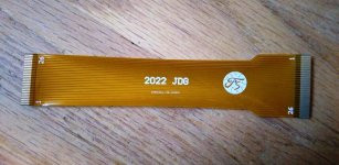
s-l1600.jpg

With this we encounter our first issue. The side the contacts are on for the 1.00 mm side are the opposite of what will be found on any typical 34-pin to 26-pin floppy adapter. This requires we use an additional piece of hardware to connect the interface. Normally this piece of hardware acts as a 26-position FFC Extension board, but we will instead be using it as a directional switcher, so we can orient the contacts on the side we need to interface with the 34-pin to 26-position adapter. This extender looks like this:
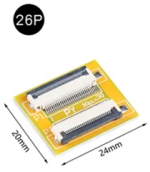
26PExtension.png

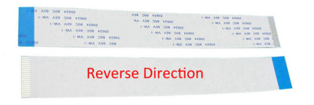
Most of the 26 pin extenders you will find are 30-pin boards with a 26-pin header attached to them like this one. That is normal. To this we attach a 26-position reverse direction FFC cable. You can use whatever length works best for you:
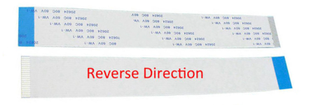
ReverseFFC.png

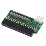
This will allow us to switch which side of the FFC the contacts are on. To this we attach the generic 34-pin to 26-position adapter, which typically look like this:
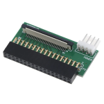
s-l1600.png
This can then be used to attach a typical desktop floppy drive or a GoTek Floppy Emulator with FlashFloppy.

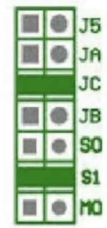
If you are going to use a GoTek Floppy Emulator with FlashFloppy, I suggest you setup the jumper block to look like this:
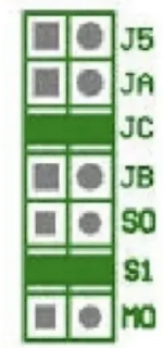
jumpers.png

You will want a jumper on S1 & JC only. In the USB drive you are using with the GoTek you will want to make sure not to have an FF.CFG or IMG.CFG files in the root of the drive. You can just put the floppy images in the USB drive root and select them as needed.

The difficulty with this setup is going to be the first cable. It is a custom designed cable made by our very own Acadiel:


They are difficult to come by and if you want to make your own, typically it will run you $100+. Rarely you can find them for sale on eBay or here, but it is a rarity. As mentioned in the thread above you can download the complete files for the adapter from the GitHub that Acadiel has kindly setup:


There is a second method, which I will document in my next post, and is typically going to be easier for most people, and involves less pieces, but it is only an option for people that are able to solder, or are willing to pay for someone to do it.
 
Last edited:
For the second method you will need:

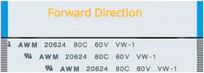
A 26-position 1.25 mm length of forward direction FFC cable
A 26-position 1.25 mm to 1.0mm adapter board
A 26-position 1.00 mm length of reverse direction FFC cable
A generic 34-pin to 26-position floppy adapter

To interface a GoTek Floppy Emulator with FlashFloppy or a typical desktop floppy drive the first step is to use a 26-position 1.25 mm length of forward direction FFC cable to connect the floppy interface on the motherboard. You can use whatever length works best for you, and It looks like this:

Forward.png

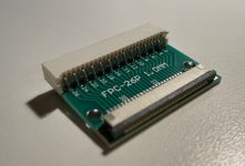
This will connect to the 26-position 1.25 mm to 1.0mm adapter board, which looks like this:

c87c540344948b4b500845f7254e.jpg

Using the adapter you would then connect the 26-position 1.00 mm length of reverse direction FFC cable. You can use whatever length works best for you, as depicted below:

ReverseFFC.png

This will allow us to switch which side of the FFC the contacts are on. To this we attach a generic 34-pin to 26-position adapter, which typically look like this:

s-l1600.png

This can then be used to attach a typical desktop floppy drive or a GoTek Floppy Emulator with FlashFloppy.

If you are going to use a GoTek Floppy Emulator with FlashFloppy, I suggest you setup the jumper block to look like this:

jumpers.png

You will want a jumper on S1 & JC only. In the USB drive you are using with the GoTek you will want to make sure not to have an FF.CFG or IMG.CFG files in the root of the drive. You can just put the floppy images in the USB drive root and select them as needed.

The difficulty with this second setup is going to be the adapter board. It is a custom designed adapter made by our very own Acadiel:

https://forum.vcfed.org/index.php?t...cable-1-25mm-to-1-00mm-now-on-github.1237299/

I have never seen this adapter offered for sale by anyone, except someone in Poland where it would be exceptionally difficult to get it to the US at any reasonable postal rate. As such, you will need to build your own. As mentioned in the thread above you can download the complete files for the adapter from the GitHub that Acadiel has kindly setup:


For fabrication of the adapter board itself I'd highly suggest OSHPark. I have done many projects with them and they are always reasonable and quick. I priced this board once on OSHPark and it came out to something like $9 for 3 boards (their minimum order is typically 3). You should have no trouble getting the connectors from either AliExpress, Mouser, etc... to complete it.
 
Last edited:
As always, please post here if you run into any problems or have questions. I will do my best to answer them.

Shoutout to Acadiel, whom without this never would have been possible.

I am looking forward to your final entry and also attempting something of my own. I hope to see how they both turn out!

I look forward to seeing what you have come up with.
 
Last edited:
Thank you for detailing what you have done to date. Your progress in gathering the information and materials to put together a replacement option has been invaluable and has clearly taken a lot of effort in working out the specifics. I should have a response of my own next weekend, once the remainder of my pieces arrive and I have time to assemble it ...or it will totally fail and that will be a story too! :)
 
Thank you for detailing what you have done to date. Your progress in gathering the information and materials to put together a replacement option has been invaluable and has clearly taken a lot of effort in working out the specifics. I should have a response of my own next weekend, once the remainder of my pieces arrive and I have time to assemble it ...or it will totally fail and that will be a story too! :)

With any luck your method won't have the critical weakness as in either of my two setups, requiring an expensive FPC cable, or the need to order a board and connectors as well as assemble them into a working adapter. For most people the first option is not reasonable from an expense perspective, and the second isn't much better for people that do not have the equipment and/or significant skill to solder such small surface mount connections. These are the critical failures of my methods. I wanted to use off-the-shelf components, but I was unable to do so. Hopefully you are either more knowledgeable or more talented at determining a solution using only off-the-shelf components.

I had also come up with a 3rd method, which was useful in that it was modular as far as what pitch size interfaces it could connect to, but as far as I can tell, it requires a piece of hardware that doesn't exist, let alone has ever been designed, being a 26-position 1.25mm FPC/FFC to 26-pin 2.54mm adapter

If I had more skill with implementing even basic designs in electronics I'd gladly make it, and release the design as Acadiel has, but unfortunately I don't.

The only other thing I could come up with is using the "34-26 Pin P1.25 Adaptor" that one can buy from FlexiDrive, with a reverse direction 1.25mm length of FFC:


Which, on its surface doesn't look like too bad of a deal, until you see they charge $25-$45 dollars shipping to the US. For the members here in Europe, it would be a much better deal given the cost of shipping. That was my main reason for trying to work with off-the-shelf components, people wouldn't need to use something like this from a single vendor for a solution. In that respect the second method is the one that has the most flexibility, with the limitation of the intermediate adapter needing to be assembled.

FlexiDrive also offers the 1.25mm to 1.00mm adapter board:


But it is the same price as the 1.25mm FFC to 34 pin adapter they sell, so it doesn't make much sense at that point, might as well just cut out the middle adapter if possible since they are the same price. Then one only needs the 34 pin adapter and a length of 1.25mm reverse FFC cabling, making life much easier.
 
Last edited:
Back
Top