• Please review our updated Terms and Rules here

Tektronix 4054/4054A Calibration Graticule

nikola-wan

Veteran Member
Joined
Mar 6, 2018
Messages
1,484
Location
Texas, USA
After posting my latest MONOPOLY game video, I wanted to try to straighten out the board - as it had significant pincushion on all four corners of the board:
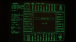
1725580350735.png

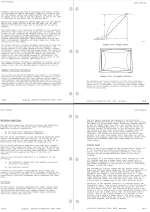
The Tektronix 4054/4054A Technical Data service manual has a description of the Geometry and Focus Correction circuitry (which is located on the Deflection Amplifier board) and Figure 12-5 shows display Pincushion Effects.
1725581257285.png

Note: the Long Axis deflection amplifier covers the X axis geometry settings of LA GEOM and LA GAIN, while the SA GEOM and SA GAIN adjust the Y axis.

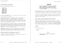
The two pages in that same service manual details how to make these adjustments on the Deflection Amplifier board:
1725581203289.png

Figure 5-7 shows the locations of the Deflection Amplifier adjustment potentiometers:
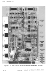
1725581528692.png

The Deflection Amplifier adjustments start with "Install the calibration graticule"!

I don't know anyone that has the 4054/4054A calibration graticule shown in the Parts and Schematics manual.

So I set out to design a calibration graticule - here is the illustration in the manual:
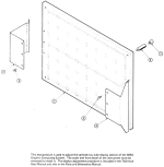


1725581777421.png

You have to remove the 4054 plastic bezel (after removing the top cover of the enclosure) and press the graticule against the CRT.

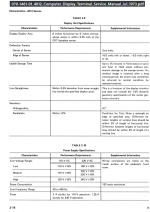
I wanted to create a 4054 calibration graticule - but I needed to know the nominal display X and Y size and didn't find it in any of the 4050 manuals.

Today I looked in the Tektronix 4014/4015 Service Manual (bitsavers.org) since the 4014 was introduced at the same time as the 4054 in 1979 and both had 19-inch DVST CRTs and found Figure 2-1 had this information on the Display Writing area:
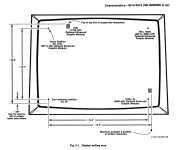
1725582231145.png

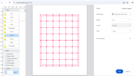
I used the 14.3" X measurement for the width and 10.7" Y measurement and made a graticule pattern using virtual-graph-paper.com online tool:
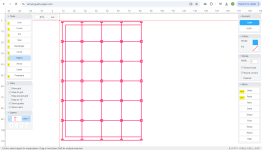
1725582616005.png
This pattern barely fits on an 8.5x11" transparency sheet in my HP Laserjet color printer. You print this half pattern twice and turn the second print around and tape it to the right side of the first page to create a full size 14.3"x10.7" calibration sheet.

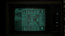
I used masking tape to place the calibration sheet on the CRT bezel - and ran my 4050 Calibration program from my Flash Drive Main Menu (it automatically determines whether you have a 4051, 4052 or 4054 and runs the correct calibration BASIC programs described in the service manuals - you press User Definable Keys (function keys) to select a particular program. I like the UDK1 Focus program - which draws the grid you see below from 0,0 to 130,100 - which is the full screen graphic area. I put the UDK key menu above 100 - where BASIC prints the blinking "F" for Full Screen.

My first calibration overlay was printed with black lines - but they are almost invisible against the display, so I changed them to red lines which do show up if you use a small flashlight or headlight like in my photo.

I had my iphone mounted on a tripod, so I could get the camera view of the pincushioning.

You can see several calibration issues in this photo:
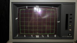
  1. The vertical lines on the far left and right are clearly bowed out in the middle
  2. The horizontal lines at the top and bottom are bowed out in the middle
  3. If you look at the calibration square to the right of the center the distance between vertical lines is almost the width of the graticule cell but the vertical lines are visibly shorter than the graticule cell - indicating the SA GAIN is too low.

4054A uneven X-Y gain and pincushion.JPEG

I recommend you take a photo from the top of the Deflection Amplifier - so you can record the current settings of the LA & SA GAIN, GEOM, and Position pots.

Remember - this is a storage CRT - so the lines you see were drawn when you pressed UDK1.
You MUST PAGE the screen then press UDK1 again after EVERY adjustment change to see the effect of that change.


I recommend looking at one of the displayed grid corners and where it intersects the graticule and then press PAGE and UDK1 to see how your last adjustment worked.
Also - make ONE small adjustment at a time - such as slightly increase or decrease LA GEOM - which should slightly change the pincushion of the far left and far right vertical lines.

The manual indicates these adjustments interact with each other - so go slow.

I had to step away after I made too many adjustments and the screen was worse than the photo above.
When I came back and took it slow - I became more comfortable on which adjustment was needed and got this much improved pincushion and gain result:
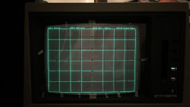
4054A pincushion calibrated.JPEG
I have attached my 4054 half-graticule SVG in a zip file that should print correctly - set margins to none and scale to default.
 

Attachments

Last edited:
  • Like
Reactions: cjs
I will also be developing a 4051/4052 calibration graticule as I need to adjust my 4052.

I did not find any viewable display area measurements in the operators or service manuals - but I did find this information in the 4012 terminal service manual which I will use to create a 4051/4052 graticule. In the text on page 2-5 it mentions approx 0.0077 inches per point spacing for the 0-1023 X and 0-779 Y axes. Dividing 1023 by 8" results in 0.0078

1725626188779.png

Here is my scaled 4051/4052 Calibration graticule - print on transparency sheet and rotate and center over your 4051 or 4052 and use masking tape to hold it to the bezel:

1725627093977.png


I put a Pincushion program in the Flash Drive Calibrate directory, but you would need to access it directly. Use the Main Menu File Browser to access the Calibrate directory and then list the files to see the file number of the Pincushion program (should be file 5). Then type FIND@5: OLD@5: RUN to execute that program to get a grid that should match the graticule!

4051-4052 Graticule SVG file attached in zip
 

Attachments

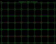
I just updated the Pincushion test program to match the graticule.

Here is the 405x Emulator screenshot:

4050 Pincushion Test.png

And I have attached a zip of the Pincushion test program.

I see that my program draws the squares at the limit of the 0-1023 by 0-779 display but my calibration graticule has cropped the outer squares and the outer line is at the display limit.

No big deal - you don't have to get all the lines aligned, you will be adjusting the center position of the Pincushion image, the X and Y size and setting the GEOM adjustment pots to get as rectangular of a image as you can.

My 4052 broke (something inside popped and display went dead) - so I'll have to repair it before I can work on the pincushion calibration.

I will also update my Flash Drive image to include my changes to the Pincushion test program and see if I can add it to the Calibrate programs as a UDK selection.
I will also make sure the Flash Drive image includes my latest MONOPOLY fixes :)
 

Attachments

Last edited:
I just updated my Tektronix 4050 Pincushion program.

I need to recalibrate the pincushion and X/Y size on my 4054A before I record a video of my Battlestar Galactica 1978 Demo program.

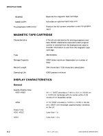
I found the 4050 Operators Manual version -01 from March 1980 Appendix B-2 lists the 4051/4052 and 4054 display "Quality Display Area"

4051/4052 11-inch DVST provides a 7.48 inch x 5.51 inch
(19.00cm x 14.00cm)
rectangle with its center with 0.25 inches of the
CRT faceplate center
4054 19-inch DVST provides a 14.00 inch x 10.50 inch
(35.56 cm x 26.67 cm)
rectangle with its center within 0.25 inches of the
CRT faceplate center.


1743712399778.png

I checked my printed graticule and it appears to be 0.25 inches higher and more than 0.25 inches wider than the quality area dimensions above.

I decided to rework my pincushion adjustment program instead of working with the printed graticule.

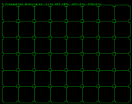
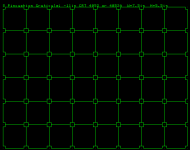
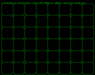
My program auto-detects whether you have a 4051, 4052 or 4054 and prints the Quality Area dimensions Width and Height above the pincushion graphic.
The Quality Area is the full window of graphics and text: X=0 to 130, Y=0,100.
Run this program and use a measuring tape or very flexible ruler to measure the width and adjust the setting to match the Quality Area for your 4050 computer.
Then adjust the height, and then center on the dot in the middle square on the pincushion graphic.
Now when viewing the display with the pincushion image - adjust the corners with the pincushion adjustment pots.
Here is my program:

Code:
100 REM generate 4050 screen graticule for pincushion correction
110 INIT
120 PAGE
130 MOVE 0,100
140 M0=INT(10*RND(0))
150 REM 1=4051, 7=4052 OR 4052A, 8=4054 OR 4054A, 5=4054 OR 54A /W OPT30
160 IF M0<>1 THEN 190
170 M$="4051"
180 GO TO 250
190 IF M0<>7 THEN 220
200 M$="4052 or 4052A"
210 GO TO 250
220 M$="4054 or 4054A"
230 PRINT "  Pincushion Graticule: -19in CRT ";M$;"  W=14.0in H=10.5in"
240 GO TO 260
250 PRINT "  Pincushion Graticule: -11in CRT ";M$;"  W=7.5in  H=5.5in"
260 FOR X=-1.5 TO 128.5 STEP 130/8
270 FOR Y=-1.5 TO 98.5 STEP 100/6
280 MOVE X,Y
290 DRAW X+3,Y
300 DRAW X+3,Y+3
310 DRAW X,Y+3
320 DRAW X,Y
330 NEXT Y
340 NEXT X
350 FOR Y=0 TO 100 STEP 100/6
360 FOR X=1.5 TO 128.5 STEP 130/8
370 MOVE X,Y
380 DRAW X+12.875,Y
390 NEXT X
400 NEXT Y
410 FOR Y=0 TO 100 STEP 100/6
420 FOR X=0 TO 130 STEP 130/8
430 MOVE X,Y
440 DRAW X,Y
450 MOVE X,Y+1.5
460 DRAW X,Y+100/6-1.5
470 NEXT X
480 NEXT Y
490 MOVE 0,100
500 END

and I attached the three different pincushion screenshots.

4051 detected
4051 pincushion.png

4052 or 4052A detected
4052-4052A pincushion.png

4054 or 4054A detected
4054-4054A pincushion.png
 
Remember - these lines are stored in the CRT phosphor on the faceplate and DO NOT CHANGE with adjustments until you PAGE the screen.

Lets add five lines to the program to use UDK 1 to PAGE the screen and rerun the program between adjustments:

Code:
1 GO TO 100
4 GO TO 120

115 SET KEY

495 PRINT @32,24:"?"
500 GO TO 490

Line 4 is UDK1 interrupt and will redraw the screen after an adjustment
Line 115 enables the UDKs
Line 495 adds a refresh print of the ? at the top left corner above the pincushion graticule
Line 500 replaces END with GO TO 490 which refresh prints ? and allows time for UDK1 to be detected

So make one small adjustment of X or Y position, or pincushion, then press UDK 1 to redraw the screen and then check the result of THAT adjustment.

Here is the updated program with the new lines:

Code:
1 GO TO 100
4 GO TO 120

100 REM generate 4050 screen graticule for pincushion correction
110 INIT
115 SET KEY
120 PAGE
130 MOVE 0,100
140 M0=INT(10*RND(0))
150 REM 1=4051, 7=4052 OR 4052A, 8=4054 OR 4054A, 5=4054 OR 54A /W OPT30
160 IF M0<>1 THEN 190
170 M$="4051"
180 GO TO 250
190 IF M0<>7 THEN 220
200 M$="4052 or 4052A"
210 GO TO 250
220 M$="4054 or 4054A"
230 PRINT "  Pincushion Graticule: -19in CRT ";M$;"  W=14.0in H=10.5in"
240 GO TO 260
250 PRINT "  Pincushion Graticule: -11in CRT ";M$;"  W=7.5in  H=5.5in"
260 FOR X=-1.5 TO 128.5 STEP 130/8
270 FOR Y=-1.5 TO 98.5 STEP 100/6
280 MOVE X,Y
290 DRAW X+3,Y
300 DRAW X+3,Y+3
310 DRAW X,Y+3
320 DRAW X,Y
330 NEXT Y
340 NEXT X
350 FOR Y=0 TO 100 STEP 100/6
360 FOR X=1.5 TO 128.5 STEP 130/8
370 MOVE X,Y
380 DRAW X+12.875,Y
390 NEXT X
400 NEXT Y
410 FOR Y=0 TO 100 STEP 100/6
420 FOR X=0 TO 130 STEP 130/8
430 MOVE X,Y
440 DRAW X,Y
450 MOVE X,Y+1.5
460 DRAW X,Y+100/6-1.5
470 NEXT X
480 NEXT Y
490 MOVE 0,100
495 PRINT @32,24:"?"
500 GO TO 490
 
Tektronix 4010 series terminals and 4050 series computers were designed so the Display Quality Area for text and graphics of X = 0-1023 and Y = 0-767 was exactly 4:3 aspect ratio (1024 horizontal zero-based addressable points by 768 zero-based vertical addressable points).

The 4014 Display Quality area appeared to allow lower case characters to descend below the bottom of the graphics area - not so for the 4050 series.
Both 4010 series terminals and 4050 computers allowed text above the graphics area - specifically to allow the PAGE FULL alert to be printed above the graphics area.

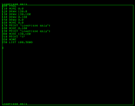
Here is my test program and screenshot captured on the 4051 Emulator - which uses the 4051 BASIC ROMs, running this simple test with the 4051 Emulator configured for single pixel text and graphics lines:

Code:
100 PAGE
110 MOVE 0,0
120 DRAW 130,0
130 DRAW 130,100
140 DRAW 0,100
150 DRAW 0,0
160 MOVE 0,0
170 PRINT "Lowercase qpjy";
180 MOVE 0,100
190 PRINT "Lowercase qpjy";
200 MOVE 130,100
210 PRINT "X"
220 HOME
230 LIST

screen - 2025-04-05T054402.718.png

Note the qpjy one 'pixel' descenders are ON the bottom graphics line and the rest of the characters are one 'pixel' above the line, but the "L" leftmost dots are on the left vertical line.

Same thing for that same text printed at 0,100 with text descenders on the top line.

Line 210 prints an "X" at 130,100 which is NOT printed there - it is printed at the beginning of the next line down from 0,100. You can see that is NOT the same location as the first line of the program listing which is printed after a PAGE command clears the screen. This is because the ROM code uses fixed spacing between each text line from the last line - which could have been printed anywhere on the screen.

The 4051 Emulator MAKE COPY key and BASIC COPY command save a copy of the 4051 Emulator graphics dot matrix buffer used to emulate the 4050 CRT phosphor storage to the browser Downloads folder. The physical 4050 computers (and 4010 series terminals) could ONLY make copies of the screen to a Tektronix 4631 Hard Copy unit by having the BASIC ROM (or terminal ROM) draw a vertical line at write-thru mode low energy across the display from left to right - and an electrode on the CRT faceplate connected to the display hardware which would amplify the signal and send it to the Tektronix single line CRT in the 4631 to transfer the image stored in the CRT phosphor to 3M light sensitive paper in the 4631!

One of my contributions to the 4051 Emulator was to increase the brightness of the text and lines by doubling the size of each dot in text or lines in the dot matrix buffer. Here is the 4051 Emulator screen copy of this same program in default mode (which doubles the dots in text and lines:
screen - 2025-04-05T060643.406.png

This tweak does not increase the resolution of the screenshot but does make the screen more visible.

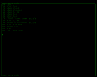
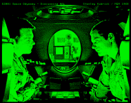
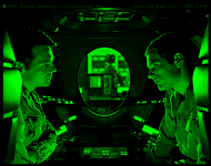
It also makes the bitmap images of the emulator "muddy" - as I found when I developed my 4050 BASIC bitmap program. Check out the comparison of my 2001 Space Odyssey - Discussing HAL with the default 4051 Emulator quad dot mode versus single dot mode:

screen - 2025-04-05T061304.269.png

screen - 2025-04-05T061401.147.png

Of course the physical 4051 / 4052 / 4054 computers only display the bitmap pictures in one dot at a time mode - however I have found that there is some bleeding of adjacent 'dots' in the phosphor which for large areas like in the two chair cushions next to the astronauts faces - that bleed further into the cushions - the detail in other areas like the faces is incredible.

A clever hardware engineer could probably design a circuit to plug into the 4050 or 4010 terminal hard copy output connector to emulate the 4631 and capture the hard copy to a file!
 
4054/4054A pincushion correction - NOTES to SELF (4051 and 4052 have 11-inch flat CRT faceplates making them slightly easier to adjust):

LA and SA pincushion adjustments (Deflection Amplifier section of Calibration in either the Parts and Schematics manual or Technical Data manual):

LA = long axis
SA = short axis

1744485051890.png
  • LA adjustment corrects the "bowing" of the long lines along the top and bottom of the pincushion illustration.
  • SA adjustment corrects the "barreling" of the short lines near the left and right of the barrel illustration.
The pincushion adjustment calibration steps in the service manuals indicate:
  • ALL the LA and SA adjustments (size, position, pincushion) affect the other adjustments :(

I had the most success by adjusting the size and position of the calibration rectangle first.

Then try adjusting the LA - using very small 'tweak' in one direction and then refreshing the calibration grid so you can determine whether CCW adjustment reduces or increases the 'bow' in the long lines at the top and bottom of the display.
When you have straightened the long axis lines - do the same thing on the SA to straighten the lines on the left and right side of the display.

I found on my 4054A that I could put a blank sheet of paper on the bezel and slide it over to the left or right side of the display to check the straightness of the SA lines.
I also mounted my iphone on a tripod with the iphone approximately user eye distance from the display.
I took photos after I thought I had a good adjustment - and tweaked the LA and/or SA adjustments until my OCD said it was good enough :)
 
PLEASE do NOT use a regular flat screwdriver to make these pincushion or other calibration pot adjustments! If the flat screwdriver slips out of your hand it could short out something when it falls.

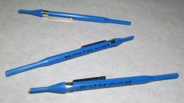
The best adjustment tool for the Deflection Amplifier pots is this kind of plastic tool - any brand:

1744543059159.png

Remove the metal clip from the tool during adjustments - so if the tool falls down into the computer - you won't short anything.

Use the end with the metal tip exposed for the Deflection Amplifier pots. The other end is for pots with exposed adjustment screws - so the tool doesn't slip off the screw.

I also suggest you take a photo of the existing pot settings before you make any adjustments.

I use an LED headlamp to be able to easily see the pots and how much of an adjustment I am making - like this one:

1744543467620.png
 
  • Like
Reactions: cjs
Back
Top