• Please review our updated Terms and Rules here

Televideo PT100 Terminal needs help, RS232 data can be received but not sent. Search Schematics

so, I'm using this thread as a bit of a "logbook" of everything I've done and checked.
If anyone else thinks of something or notices something or has an idea.

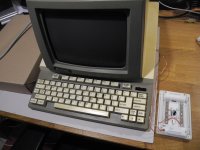
I have now "turned" the PT100 around and can then access the board to measure when it's live, but it's then difficult to use the keyboard (I use cardboard from Amazon as insulation :) )
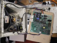
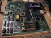
DSCN9993.JPG

I've already replaced the EPROM, no effect.
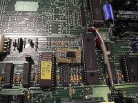
DSCN0007.JPG

I've replaced the two RAM ICs, no effect.
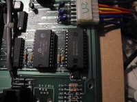
DSCN0009.JPG
I've replaced the MC1488 and MC1489 and also measured the MC1488:
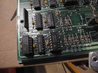
DSCN0006.JPG
Pin1: -VCC - 12.12 V
Pin14: +VCC + 11.92V is OK.

The serial input via an external laptop works.
Pin1 from the MC1489 goes to Pin-3 of the SUB-D-25

The serial output does NOT work, Pin8 from the MC1488 goes to Pin-2 of the SUB-25
The error remains, as soon as I press a button on the PT100, it freezes and can only be revived by switching it off for at least 2 seconds.

The system voltages can be easily measured on the red plug:
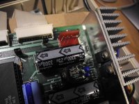
DSCN0005.JPG
12.12V / 5.12V / GND / - / -12.11V

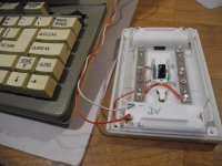
The last possibility I see is that the 3V from the battery is the cause (unlikely).. you can't measure 3V there without a battery, because it's not a rechargeable battery and only voltage can be introduced.
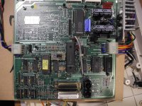
DSCN0008.JPG
 
But you haven't got the RS232 loop-back connector plugged in...

What is the status character on the lower left-hand of the screen?

Is it an 'H'?

Dave
 
Hello Dave,
I also tested a loopback connector... but that doesn't help at all!
YOU CAN'T PRESS or SEND A SINGLE LETTER WITH IT:
Do you have a Televideo PT100?
It shouldn't "crash" or freeze WITHOUT any adapter, without any printer, without any PC.
 
No I don't have a PT100, but I have 50 years experience in sorting out communications problems. In fact, I was on a nuclear plant today diagnosing a serial issue...

If you don't have the RS232 loopback connector in place, then this is another link in a chain that can stop the character being transmitted if the terminal is expecting a CTS handshake signal.

If you can't see a character being transmitted, is the terminal trying to transmit it but can't because of the lack of a CTS, or is the firmware crashing or what?

This is why I asked about the trminal status character. If it indicates 'H', and the 'H' disappears when you plug in the loopback connector, this indicates to me that the RTS-CTS link needs to be made for the terminal to transmit a character.

If you don't want to follow this train of thought, that is fine by me...

Dave
 
Hello Dave,
I don't doubt your abilities and have never been against using a look plug.
I've tried it several times and wrote that I did it, but unfortunately it still didn't work. Hence my repeated comments.

Here are some pictures of proof
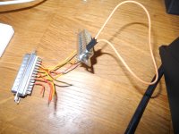
This is my loop plug (with the known bridges)
DSCN9969.JPG
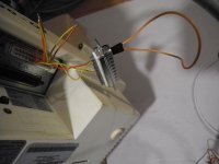
and this is then plugged into the PT100
DSCN9970.JPG

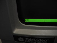
and as soon as I press a key, YES, "H" appears and the computer freezes (crashes) as I've been trying to describe all this time.
DSCN9971.JPG
Maybe my English isn't that good either, because I always have to translate, because unfortunately English isn't my native language

I also tried replacing the 3V, I have an external LED night light here, I tapped 3V from there.
DSCN0021.JPG+DSCN0026.JPG+DSCN0024.JPG
And with that, the internal data storage for the parameters is now working.
I wrote rubbish in one line and it is now retained.

I also cut off all the old capacitors in the 1488/1489 area on one side and measured them for short circuits and the capacitance was all OK.

I really don't know what to do anymore and I'm afraid it's the internal custom chip.

best regards, Mikel
 
Have you checked the state of the RTS/CTS signal both before and after pressing a key - with the loopback installed?

The RTS should go via an RS232 tramitter buffer to the connector, looped back to the CTS signal, and back through an RS232 receiver buffer.

We need to check whether this is happening or not.

With the loopback plug installed, you should not be seeing the 'H' status character.

If you are seeing the 'H' status character, the terminal will not be transmitting a character at all...

Dave
 
Incidentally, now you are above 10 posts, you can update your profile with your location (if that is something you wish to do)?

Dave
 
Hello ladies and gentlemen!

With some pride and great joy, I can announce that the error has been found and this PT100 is working perfectly again.

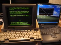
The personal terminal can now exchange data with another PC via a null modem cable, or with a WIFI modem to the Telenet.

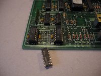
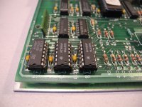
Just briefly, what was the error? The third MC1488/1489 that was NOT socketed.
DSCN9992.JPG+DSCN9998.JPG
I suspected this as a last possibility, with a circuit diagram I would certainly have been able to identify the inputs and outputs better directly. ;)
I replaced it and now the device works perfectly.

Thanks again to @Steve Toner for the instructions and also to Steve for the EPROM.
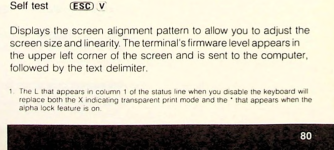
It is interesting that Steve's EPROM also has the self-test with ESC-v integrated, which my EPROM does not have.

Bildschirmfoto 2024-10-18 um 18.57.27.png

(I had put my own EPROM back in, I don't know now whether if the other EPROM would work completely for me)
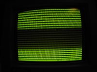
But with this EPROM i can made hardware test, a page full of "HHHHHH" appeared but without a revision being displayed, as it should have.
DSCN9972.JPG

and now a few nice pictures..
DSCN0010.JPG+DSCN0013.JPG+DSCN0019.JPG
Best wishes and thanks

MIkel

DSCN0036.JPG
 
You can measure the resistance from the RS232 connector pins to the MC1488/1489 pins using a multimeter.

This is how you can reverse engineer the schematic of an unknown machine. The datasheets for the devices tell you which pins are the inputs and outputs.

The 1488 is a driver, so the output pins will be connected to the RS232 connector pins (if they are connected).

The 1489 is a receiver, so the RS232 pins will be connected to one of the two inputs for each receiver gate (if they are connected).

Basically, you use one multimeter probe on (say) pin 2 of the RS232 connector and go around all of the input and output pins of all of the 1488 and 1489 devices until you find the lowest resistance (in effect, a 0 Ohm resistance as this would indicate a direct PCB track).

Dave
 
I know exactly which IC it was, it was the second MC1489. (receiver)
For fun, I'll measure directly on the IC again... and not install it again.
it seems as if the two ICs MC1489 were shared for printer and main port at the same time.

But not anymore, after that the MC1489 will go in the trash ;)

Mikel
 
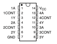
1 off 1488 will give us 4 output drivers (max).

2 off 1489 will give us 8 input receivers (max).

On the output side I get:

Main TX.
Main RTS.
Printer RTS.

I suspect Printer TX should be present here and not Printer RX. This may be a fault in the original documentation!

On the input side I get:

Main RX.
Main CTS.
Main DSR.
Printer CTS.
Printer DSR.

I suspect the other output signals are hardwired to resistors.

By my mathematics, that is four outputs (one off 1488) and five inputs (more than one 1489).

Dave
 
I measured the defective MC1489 IC again with the ohmmeter.
There are only two low-resistance connections between pins 2-5-7.
CNT1+CNT2 go to GND. (if I see it correctly, these are not normally used at all).

It may of course be the case that these actually have to be high-resistance. (I can check again on a "healthy" IC).
Anyway... the MC1489 is now being disposed of and I am happy.Bildschirmfoto 2024-10-19 um 13.25.44.png
 
I didn't mean to test the faulty 1489.

I meant to see which RS232 signals it was designed to receive.

Dave
I suspect cts or rts. Those 1489 are very susceptible to damage. When I worked for NERC we kept plenty of spare as our place in Wallingford (actually Crowmarsh/Gifford) was right next the Thames which seems to attract thunder. As we had lots of terminals and a PACX terminal switch we had lots of these...
 
I suspect it would have been CTS (a 1489 is an input).

This will support my assertion that the issue was a hardware handshake issue.

Dave
 
I know it works fine now.

But you do not know why it works fine (apart from a broken 1489).

You were citing the hardware handshake signals as not to blame for your so-called 'crashing'.

I think that there wasn't a 'crash' but this is the expected behaviour with the CTS hardware handshake signal in the wrong state (as would be the case with a faulty 1489 - assuming this device contains the CTS handshake signal).

This is your ideal opportunity to find this out...

I have also indicated the best way of reverse engineering the schematic for the unit (well, the serial interface part of it at any rate) for when it goes faulty next time.

Dave
 
Hello Dave, but I also reported also for other users. ;) and yes, I noticed that you still don't believe in a "crash".

As a final attempt at an "crash" explanation: no matter what the hardware handshake lines are like, it must be possible to get back to the parameters by using "EXIT"-key. but that doesn't work.

We both differentiate between cause and effect.
I have had the "electrical" -Cause sought, and not "the effect".
And it was the defective MC1489, which, when addressed, pulled a high to low or a LOW to high.
This IC was now sent to IC heaven.

The error has now been completely removed.
I will also take another connect a real old analog modem, there we can see all the displays on the LEDs at the front.
But I am sure that everything works as expected.

greetings... and i am happy,.. Mikel
 
Back
Top