Hugo Holden
Veteran Member
One thing that really bothers me is when some piece of apparatus has a line power cord dangling out of it. Both my AIM-65 and my PET has this. The cord is always dangling down and trailing behind like the Tail on an Alien moving them around.
I much prefer standard IEC panel line power connectors. On many of my machines I have fitted these and eliminated the power cord. Then I just need a few IEC power cords.
I had been meaning to convert my AIM to 230v, it just requires changing the transformer's primary connections.
The power cord on the AIM is a thick ( 9mm diameter ) heavy duty affair that looks suited to running a concrete mixer.
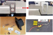
So I looked at fitting an IEC Connector to the AIM-65:
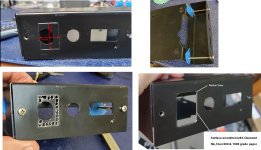
It was complicated by the fact the original panel work, in the region where the power cord entered and original fuse holder was, is quite narrow on each side, only about 6.6mm. Photos attached.
The square hole there (where the fuse-holder was) is 16mm wide, and I did not want to widen it and possibly weaken the panel, which would have happened if I made the usual cut-out for the IEC connector which is about 20mm wide. It would have required 2mm cut of each side, thinning the the width to 4.6mm on each side. But there was another complication; if the connector was mounted there, on the front panel surface as usual, the upper flange of it would interfere with the case cover, and then I would have to cut some plastic out of the case. I decided therefore to go down the road of removing as little material as possible. And again if it was mounted on the front it could not easily be moved down, to avoid the case interference, because the pcb sits just under the rear of it too.
I noticed a couple of things though, one is the width of the internal socket was 16.1mm, and the panel hole already 16mm. So I figured I could mount the IEC Connector on the rear of the panel with some small rectangular washers which are about 1.2mm thick, this to allow for the flange on the front face of the IEC connector.
Also I measured the length of the IEC plug, they are a little different on different brands and some have a flange around the base and some don't. I found the depth of the IEC connector when mounted on the rear of the panel was 19mm from the panel exterior surface. The plugs ranged from 18mm to 20mm for the versions with flanges, so in the worse case there was only a 1mm loss of projection of the plug into the socket mounting it this way, but for most plugs without flanges no effect at all. So again, but for a different reason, I decided not to file away the aluminium to allow for flanged plugs.
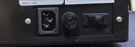
Of course a different primary fuse had to be added, I placed it beside the power switch and its upper surface , the added insulators sit just a little lower than the top of that original switch. The surface is actually flush nearly with the lower surface of the pcb. I threaded a hole in the side wall using a Roll tap (these create incredibly strong threads by compressing the aluminium, rather than but cutting it away. (To do it on a thick panel like this, start with a cutting taper tap for a couple of turns then change to the Roll tap). The screw is a 4-40 UNC, 1/4 inch length with a lock washer too. It it important to put insulation around the fuse holder.
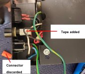
I also tied the line wiring down under the board to make it more tidy and so it wasn't rubbing on the lower pcb surface. In the orginal design, the wires were just loose, and touching the lower pcb surface in places. That could be awkward if the insulation failed on a sharp spike from a pcb component and injecting line voltages into the pcb ! The hookup wire I used is very good silicone rubber covered made by Permanoid in the UK (shame they stopped making it, it is a harsh environment wire), it has normal strands unlike the fine multi-stranded type and has thick insulation. It is great because it is not melted, even by high soldering iron temperatures. The original wire wasn't bad either it was small OD white Teflon coated, I kept a piece of it that connects from the fuse to the switch, because it already had a spade terminal fitted.
Now I think I might have a look at the PET.
I much prefer standard IEC panel line power connectors. On many of my machines I have fitted these and eliminated the power cord. Then I just need a few IEC power cords.
I had been meaning to convert my AIM to 230v, it just requires changing the transformer's primary connections.
The power cord on the AIM is a thick ( 9mm diameter ) heavy duty affair that looks suited to running a concrete mixer.
So I looked at fitting an IEC Connector to the AIM-65:
It was complicated by the fact the original panel work, in the region where the power cord entered and original fuse holder was, is quite narrow on each side, only about 6.6mm. Photos attached.
The square hole there (where the fuse-holder was) is 16mm wide, and I did not want to widen it and possibly weaken the panel, which would have happened if I made the usual cut-out for the IEC connector which is about 20mm wide. It would have required 2mm cut of each side, thinning the the width to 4.6mm on each side. But there was another complication; if the connector was mounted there, on the front panel surface as usual, the upper flange of it would interfere with the case cover, and then I would have to cut some plastic out of the case. I decided therefore to go down the road of removing as little material as possible. And again if it was mounted on the front it could not easily be moved down, to avoid the case interference, because the pcb sits just under the rear of it too.
I noticed a couple of things though, one is the width of the internal socket was 16.1mm, and the panel hole already 16mm. So I figured I could mount the IEC Connector on the rear of the panel with some small rectangular washers which are about 1.2mm thick, this to allow for the flange on the front face of the IEC connector.
Also I measured the length of the IEC plug, they are a little different on different brands and some have a flange around the base and some don't. I found the depth of the IEC connector when mounted on the rear of the panel was 19mm from the panel exterior surface. The plugs ranged from 18mm to 20mm for the versions with flanges, so in the worse case there was only a 1mm loss of projection of the plug into the socket mounting it this way, but for most plugs without flanges no effect at all. So again, but for a different reason, I decided not to file away the aluminium to allow for flanged plugs.
Of course a different primary fuse had to be added, I placed it beside the power switch and its upper surface , the added insulators sit just a little lower than the top of that original switch. The surface is actually flush nearly with the lower surface of the pcb. I threaded a hole in the side wall using a Roll tap (these create incredibly strong threads by compressing the aluminium, rather than but cutting it away. (To do it on a thick panel like this, start with a cutting taper tap for a couple of turns then change to the Roll tap). The screw is a 4-40 UNC, 1/4 inch length with a lock washer too. It it important to put insulation around the fuse holder.
I also tied the line wiring down under the board to make it more tidy and so it wasn't rubbing on the lower pcb surface. In the orginal design, the wires were just loose, and touching the lower pcb surface in places. That could be awkward if the insulation failed on a sharp spike from a pcb component and injecting line voltages into the pcb ! The hookup wire I used is very good silicone rubber covered made by Permanoid in the UK (shame they stopped making it, it is a harsh environment wire), it has normal strands unlike the fine multi-stranded type and has thick insulation. It is great because it is not melted, even by high soldering iron temperatures. The original wire wasn't bad either it was small OD white Teflon coated, I kept a piece of it that connects from the fuse to the switch, because it already had a spade terminal fitted.
Now I think I might have a look at the PET.
Attachments
Last edited: