• Please review our updated Terms and Rules here

Trouble with my PET(unia)

Nivag Swerdna

Veteran Member
Joined
Jul 17, 2020
Messages
740
Location
London, UK
So my beloved PET has started to act strange... which is rather annoying as I'm trying to test some bits and pieces before sending them out to people...

It won't reliably start unless I put my finger on pin 27 of the CPU...
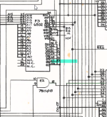
1693401864154.png

If I leave my finger there it performs perfectly.

Could this be a problem with one of the transceivers? or a CPU issue?

Very annoying.
 
Obviously it could be a bad socket connection and physical pressure on the pin improves it ? Is it in a socket?

Interesting though. How did you discover that, just by accident touching every pin ?

If it is not a bad socket connection; when you touch the pin your body adds about 100pF capacitance as well as injecting noise, typically mains borne hum signals, but, not much because the impedance of a data line like that, most of the time is fairly low.

The added capacitance could have a number of effects, including slightly slowing the rise and fall time of the pulses there. Or, perhaps it is suppressing another high frequency signal or transient there, that should not be there. Perhaps there is some cross coupling between tracks due to corrosion on the pcb. There could be quite a few explanations.

I would start trying some experiments to see if I could duplicate the problem in a controlled manner without using a finger. Put a 100pF capacitor from pin 27 to ground. Try putting an additional 0.1uF capacitor across the 6502 power pins directly to make sure it is properly bypassed at radio frequencies. Put a wide bandwidth scope on the pin and look for any irregularities, such as incorrect logic levels or high frequency interference. Probably best with a x10 probe, the capacitance of a x1 probe might kill the problem. Obviously if it was in a socket you would have tried another CPU by now ?
 
Obviously it could be a bad socket connection and physical pressure on the pin improves it ? Is it in a socket?
Revisited... Physical pressure doesn't seem to help.

Interesting though. How did you discover that, just by accident touching every pin ?
Damp finger is in my diagnostics kit. Yeap moved finger around. Seems most effective near pin 27.

When I have time I will whip the PCB out and look for issues. This poor motherboard is used for every gadget I have made so there has been quite a lot of swapping and to be honest pressing down as things are swapped in and out.

I'll post a photo of the socket....
 
If you've been swapping stuff in and out of the original socket it's probably toast; even "decent" standard DIP sockets aren't designed for very many cycles. If you've ever stuck any kind of piggyback board into the socket it's *especially* likely to be dead; such boards usually use machine pins that are fatter than IC pins.
 
If you are going to be using your PET as a development or test machine I would advise making a little carrier board adapter using a ZIF socket.

Dave
 
Seems most effective near pin 27.
That suggests another possibility if multiple places on the pcb affect whether or not it starts up, with your body's capacitance attached and noise signals injected by your body into the circuitry:

The crystal in the master oscillator could have lost activity and be on the borderline to start oscillating. Check its function and/or try another crystal. Once it starts though, it will usually stay running, it is just sometimes as the crystals age, depending on factors like temperature, vibration, electrical noise etc, they can go reluctant to start.
 
It won't reliably start unless I put my finger on pin 27 of the CPU...

Just to make it crystal clear here; when you say it "won't start", do you mean it doesn't reset properly on power-on and get to the BASIC prompt, but once it's past that it runs fine if you take your finger away, or do you mean it doesn't *run* if you don't have your finger there? (IE, it'll stop/crash/glitch if you pull your finger away once it's started.)

I had a PET that stopped resetting reliably and it was one of the ceramic disks in the 555 reset circuit. It was also the kind of problem that randomly touching the motherboard somewhere might have an affect on. Assuming you have access to an oscilloscope or logic probe it would definitely be worth checking the basics like if RESET transitions from low to high shortly after power-up, that the input clock to the CPU is ticking (at around 1Mhz, assuming you have the ability to measure the frequency), etc, etc. If that 555 circuit isn't quite doing its job it might not be pulling RESET low enough/long enough/whatever to get the CPU reliably running on power-on.
If there was some delay in the Xtal osc starting, the 555 which operates independently of everything else, could have completed its 1 sec reset cycle after power up and then the CPU wouldn't get a reset, even if the Xtal osc was running or started later it probably wouldn't boot normally, if at all. Though I have not tried stalling the xtal osc 'till after the 555 has finished its 1 sec timing cycle, that would be an interesting experiment, I suspect though, the outcome of which would be equivalent to not having the reset cycle of the 555 at all.

It would be an interesting observation, with the fault present, whether or not the random screen appears on the VDU, or not ? at power up, if it did, then the master oscillator would have to be running at that time or the VDU would be blank, the test though has to be done once the VDU is initially warmed up, switching on from cold ....doesn't show it. (wouldn't you know it ? to quote David Gates from Bread)

The 555 circuit does need checking. The most likely part to give trouble is the Tant timing capacitor. Ceramic capacitors like the 0.1uF one on the trigger pin 2 of the 555 are generally more reliable, though they sometimes can fail, generally their M/O when they do, is to go short circuit, which generally produces a constant rather than intermittent fault. The 555 timer IC , especially the original NE555N made by Signetics are generally super reliable and I'd be happy to put one in a Pacemaker, though later generation and cmos 555's I have found less reliable.
 
Last edited:
I've taken all the above onboard; just need to find some time to experiment... will probably be the weekend. Thanks all.

1693557409471.png

PS
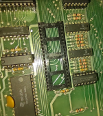
Please don't mention the discolouration in the top left... it's a huge embarrassment! That was in my early days of hot air for chip removal.
 
That 40 pin socket does look awful.

I pretty sure on that design of socket, you can lever off the plastic shroud, leaving individual socket claws exposed.

To do it, if you use something like a flat blade screwdriver, you need to cut out a small piece of cardboard to put between the screwdriver blade and the pcb surface, otherwise the metal will dig into the pcb surface and leave marks, or worse damage tracks.

Once the plastic shroud is removed, you can then remove each socket pin one by one with the soldering iron.

After that apply a little fresh solder to each hole/pad and then use the one shot solder sucker. The holes will be extremely easy to clear with no pins in them. Then do the usual cleanup with cue tips and IPA or similar.

I would suggest fitting a new dual wipe socket (of the construction Ruud cited), not a round machine pin type.

An awful lesson to learn about hot air guns. I never use them because they can induce diffuse thermal damage.
 
I haven't had time to look at this properly... but I looked at it improperly...

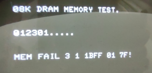
Put a 6502 back in the CPU socket; PETTESTER in H7 and...

1695304505957.png

I wonder if that is a clue?
 
I wish I could help more with this.

My memory test for the PET works differently. What I do is dynamically substitute in good working SRAM for the lower 1k of memory , from 0000h up to 03FFh. This ensures that BAISIC works and boots normally (excluding other faults that is).

Then I use some custom programs that are block moved from ROM, just below 03FFH.

These fill the memory to be examined from 0400h and above to wherever up to 7FFFh for a 32k PET, with byte patterns or a byte of your choice.

Then I simply examine the DRAM memory with the TIM, to find out what has gone wrong. The defective byte patterns give the game away, but there are some interesting variations that occur, due to the type of faults in the DRAM chips.
 
Last edited:
Back
Top