• Please review our updated Terms and Rules here

TRS-80 model 1 issues

Drayson

Member
Joined
Jun 29, 2024
Messages
21
Location
Oklahoma
Hello, I just recently ordered an original TRS-80 set from eBay. It's usable and works for the most part, but there are some issues that would be nice to fix.
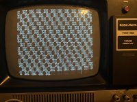
  1. Picture is inconsistent: This is the biggest one that makes this thing harder to use. Whenever I turn it on, the picture appears in the correct position at first, but then starts moving around erratically and sticking past the left border of the screen. For some reason, this didn't happen when I powered it up for the first time, but it's been happening since.
  2. Character "mirroring": This one I don't mind too much, but every single character appears with the top half repeated underneath them. It was also like this in the eBay listing, I have no idea if it's a normal thing or not.
  3. Exclamation points: Sometimes, there's these exclamation points that show up randomly all over the screen, with more of them showing up the longer I use it. I have a feeling this could be more or less a feature, but I don't know exactly what it is.
Here is a video I've attached to show exactly what's going on:
 
Hello, I just recently ordered an original TRS-80 set from eBay. It's usable and works for the most part, but there are some issues that would be nice to fix.
  1. Picture is inconsistent: This is the biggest one that makes this thing harder to use. Whenever I turn it on, the picture appears in the correct position at first, but then starts moving around erratically and sticking past the left border of the screen. For some reason, this didn't happen when I powered it up for the first time, but it's been happening since.
  2. Character "mirroring": This one I don't mind too much, but every single character appears with the top half repeated underneath them. It was also like this in the eBay listing, I have no idea if it's a normal thing or not.
  3. Exclamation points: Sometimes, there's these exclamation points that show up randomly all over the screen, with more of them showing up the longer I use it. I have a feeling this could be more or less a feature, but I don't know exactly what it is.
Here is a video I've attached to show exactly what's going on:
Simplest explanation for extra half-characters is that the DLY L8 signal (which should really be called the DLY L8* signal) is not getting propagated from Z27.11 to Z26.12. If the trace connecting them is somehow broken and the Z26.12 input is unconnected to anything, I would expect Z26 to most likely act the same as if it were getting a high input, which would result in the top-half of characters being repeated. Of course, the problem could also be that Z27 or Z26 need replacement. I'd start by checking, with the power off, the resistance between those pins (which should be zero).

I said that was the simplest explanation after looking at the schematic. But after looking at photos of both sides of the board, I'm a bit confused, because I can't make out where the trace is that connects those pins.

Anyway, sorry my only input is about your least-pressing problem.
 
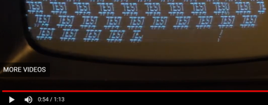
Okay, here's something about your other not-the-most-important problem: the exclamation points are the result of the zeroth bit of a space character sometimes erroneously getting stored as a one rather than a zero. The same thing will occasionally cause a "T" to get stored as a "U", but won't ever affect "E" or "S" because those have odd character codes. Here's a screenshot of a "TEST" coming out "TESU" (near the upper right corner):
1723663884121.png
This likely means the input on pin 11 (data-in) of Z48 is intermittently disconnected. That's the D0 signal generated at Z76.11. The trace is extensive, because it's a data bus line, but the problem is probably near Z48. I'd start by checking the connectivity from the pin to the solder point at the bottom of the backside of the board (the solder point at the bottom center of this pic):
1723665533306.png
 
And on your big problem: I don't understand much analog stuff, but I would try fiddling with the horizontal-hold knob on the back of the video display and hope that magically fixes things.
 
Simplest explanation for extra half-characters is that the DLY L8 signal (which should really be called the DLY L8* signal) is not getting propagated from Z27.11 to Z26.12. If the trace connecting them is somehow broken and the Z26.12 input is unconnected to anything, I would expect Z26 to most likely act the same as if it were getting a high input, which would result in the top-half of characters being repeated. Of course, the problem could also be that Z27 or Z26 need replacement. I'd start by checking, with the power off, the resistance between those pins (which should be zero).

I said that was the simplest explanation after looking at the schematic. But after looking at photos of both sides of the board, I'm a bit confused, because I can't make out where the trace is that connects those pins.

Anyway, sorry my only input is about your least-pressing problem.
Okay, here's something about your other not-the-most-important problem: the exclamation points are the result of the zeroth bit of a space character sometimes erroneously getting stored as a one rather than a zero. The same thing will occasionally cause a "T" to get stored as a "U", but won't ever affect "E" or "S" because those have odd character codes. Here's a screenshot of a "TEST" coming out "TESU" (near the upper right corner):
View attachment 1284722
This likely means the input on pin 11 (data-in) of Z48 is intermittently disconnected. That's the D0 signal generated at Z76.11. The trace is extensive, because it's a data bus line, but the problem is probably near Z48. I'd start by checking the connectivity from the pin to the solder point at the bottom of the backside of the board (the solder point at the bottom center of this pic):
View attachment 1284724
And on your big problem: I don't understand much analog stuff, but I would try fiddling with the horizontal-hold knob on the back of the video display and hope that magically fixes things.
Thank you so much for the response. Funnily enough, I have managed to track down the picture instability problem to Z5. I have a quad NAND gate with a slightly different pinout, so I just wired that up as a temporary solution and it worked IMG_0146.jpeg
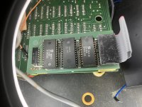
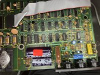
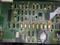
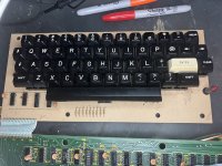
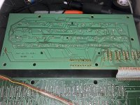
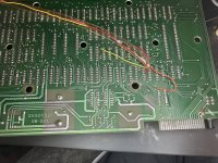
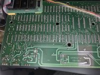
However I am having trouble pointing out the things you mentioned. Here are some pictures of my specific model so you have more to go off of (don't mind Z5 being missing):IMG_0135.jpegIMG_0136.jpegIMG_0137.jpegIMG_0138.jpegIMG_0140.jpegIMG_0141.jpegIMG_0142.jpeg
 
Thanks for the pics.

Regarding extra half-chars: I still can't make out how the trace connects Z27.11 to Z26.12 like the schematic says it does. But the traces do seem to match the schematic up to Z27.11, so perhaps next you should check that that output is correct. It should be a 1320 hz square wave -- one period per the 22 character rows (including the 6 rows blanked during vertical refresh) per 60 hz video frame. It's 2/3 high voltage and 1/3 low. So if you don't have a scope you can check the DC voltage from ground at pin 8 to pin 11 and it should be about +3V. Pins 10 and 12 should have the opposite wave, so about half the DC voltage. See PDF page 42 (pages 31-33) of the Samfacts for lots of waves and voltages you can check:
1724089970615.png
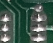
On the VRAM bit-zero input occasionally incorrectly being high (probably meaning it's occasionally disconnected, or insufficiently connected): I miscounted chips on the backside of the board, and what I thought was Z48.11 was actually Z47.11. Here's the real Z48.11 on your board, in the lower right of this crop:
1724090606842.png
Perhaps there's a small but measurable resistance between the pin and the solder point at the top? Whether you can measure it or not, running a jumper wire between those points might fix the problem. Or run a jumper all the way to the source, which is Z76.11. Of course, it could also be that Z48 needs to be replaced.
 
I see in your Photo's that IC Z5 is missing. It is supposed to be installed to get the Model 1 working properly.
Is it still missing?

Larry
 
I see in your Photo's that IC Z5 is missing. It is supposed to be installed to get the Model 1 working properly.
Is it still missing?

Larry
Don't worry about that, I removed it myself because it was faulty and causing one of the issues I mentioned.
 
Back
Top