• Please review our updated Terms and Rules here

TRS-80 Model 1 won't power when attached to Expansion Interface.

DistantStar001

Experienced Member
Joined
May 8, 2019
Messages
178
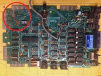
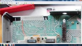
As the title says, TRS-80 model, pretty much stock. 1978 date codes, original High-tek keyboard, cassette mod (RadioShack installed), and Level 2 BASIC in 2 ROMs on a daughter board. Catalog number 26-10044D-1. As far as I can tell, it's never been messed with aside from a minor repair for the horizontal sync. However, when plugged into an expansion interface the +5v ine dissappears! -5v and +12v are fine. The same thing happens when connected to a buffered connetion ribbon. Any ideas?
 
Check the expansion interface J2 connector for the buffered interface power mod (ORANGE WIRE). This routes +5V to a connector on J2 that is normally GND. If the mod is present, +5V from the expansion interface is grounded when a ribbon cable is plugged in. This is supposed to be used with the buffered expansion cable (with box) as it provides power to the buffer circuit in the box and has the ground line to the model I disconnected. It should work correctly with the buffered expansion cable (with box); if not, you can temporally unsolder the ORANGE wire and connect the computer with a plain ribon cable to see if this is your problem.
>> Charles
 

Attachments

  • TRS80.jpg
    TRS80.jpg
    222.8 KB · Views: 25
Check the expansion interface J2 connector for the buffered interface power mod (ORANGE WIRE). This routes +5V to a connector on J2 that is normally GND. If the mod is present, +5V from the expansion interface is grounded when a ribbon cable is plugged in. This is supposed to be used with the buffered expansion cable (with box) as it provides power to the buffer circuit in the box and has the ground line to the model I disconnected. It should work correctly with the buffered expansion cable (with box); if not, you can temporally unsolder the ORANGE wire and connect the computer with a plain ribon cable to see if this is your problem.
>> Charles
Sadly, no. this mod is not present on my board.
 
OK. Looking at my unit, it appears that I have the same board you have with a few notable differences:

- First, Mine lacks the afore mentioned mods seen in your pic. The ones for the buffered cable.
- Second, mine has no solder mask on the component side (not sure what that's about).
- Finally, third, the two left most pins (as oriented in your picture) are bridged. This was not a mod and appears to be part of the original PCB. However, I have found no other examples of it online.

I checked the continuity of on the afflicted Model 1 and there is no corresponding bridge on those pins except when the interface (or buffered cable) is connected. The same for the working unit. Further when I replicated this bridge on the afflicted Model 1 without anything else attached, the computer wouldn't boot. However, this had no effect on the other computer. So, figuring I could always put it back with a solder blob, I decided to cut the bridge. Now the Expansion works with both Model 1s as expected! Any explanations? Don't get me wrong, I'm glad it works, but I'd like to know what that bridge was about in the first place.
 
From the Radio Shack Expansion Interface service manual the connector "J2" has pins#37 and pins#39 originally connected to GND. In later Radio Shack revisions they modified the board to isolate pin#37 and connect it to +5V for the buffered cable power source. There were three expansion interface board modifications before they redesigned the board...Original, buffered
cable mod, and the RAS/CAS DIN plug mod. Your board could be any of the three mods or maybe someone reversed the mods to get it to work with an original Model I. The solder blob connecting #37 to #39 would have returned it to the original configuration as described in the service manual. As to the solder mask, some boards had it while others did not. Glad you
got your machine working in any event.
> Charles
 

Attachments

  • TRS_01.jpg
    TRS_01.jpg
    533 KB · Views: 12
  • TRS_02.jpg
    TRS_02.jpg
    451.6 KB · Views: 12
Back
Top