• Please review our updated Terms and Rules here

TRS-80 Screen Printer - Are There Schematics Out There?

Dubis7

Experienced Member
Joined
Mar 20, 2018
Messages
105
I need to build a cable for mine as part of the restoration project, but there's some discrepancies between the expansion port on the Model 1 and the Screen printer. Namely, the Model 1 port is a 40 contact card edge and the printer has 50, so this clearly isn't a one to one setup.

Does anyone have schematics, or possibly a cable I could reference?
 
You can easily make a parallel cable for the Model 1. You just need a 34 Pin Card
Edge Connector, some 34 Conductor Ribbon Cable, and a 50 Pin Centronics
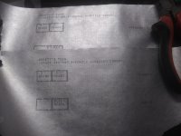
Connector that is for Ribbon cable. The Pinout for J4 is on the schematics.
Pin 1 should go to Pin 1 on the Centronics. One conductor will need to
be crossed and laid down on the Centronics Connector on a Specific Pin.
I don't have my Model 1 Cable handy but if you draw out the connectors,
on paper you can see what needs to be crossed. I think it's Printer BUSY
if I am remembering correctly. (I made mine back in the mid 1980's.)


REF: CENTRONICS CONNECTOR: https://old.pinouts.ru/ParallelPorts/Printer_pinout.shtml

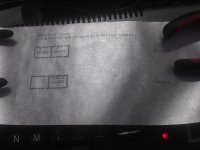
So, when you draw out your connections you will use the Model1 connector on the left,
as per attached Schematic, and the Centronics connector on the right. Just draw lines
between the same signals, and wire it that way.


Larry
 

Attachments

  • M1p82.pdf
    677.8 KB · Views: 6
Last edited:
Great, thank you! I didn't realize it was just standard Centronics connections.
 
You can easily make a parallel cable for the Model 1.

Great, thank you! I didn't realize it was just standard Centronics connections.

It's not!!!

The Screen Printer is not a parallel printer. It's a really weird bird that uses DMA (by pulling the TEST line on the TRS-80's expansion port) to directly scrape the Model I's video memory when the button on the printer is pushed. Unfortunately the regular user manual for that doesn't seem to have any schematics or pinout for it. I have a vague memory that there was an article in an issue of 80 Microcomputing that *may* have had some details, but this is a memory around 30 years old.
 
This is probably the article I remember from 80 Micro; it's about modifying the Screen Printer so it works properly for TRS-80's that have lowercase modifications, but it also has some general information about how the thing works. There's a photo in the article of the PCB in the middle of the original cable that changes it from 40 to 50 pins, because the modification included adding a diode to one of the lines. It looks like the board had little to nothing in the way of active components, it just rearranges pins, but I imagine a photo of only one side of it isn't going to be enough to work from. If someone else has a screen printer and is willing to pry open the box around that adapter that would be the most direct way to getting the answers you need.
 
Ahhhh. I figured the centronics connection was wrong. As stated, it's going from 40 pins to 50 pins. Eudimorphodon is correct in the operation as far as I can tell after taking it apart and looking at the circuit.

The first board shown in that article looks very similar to the one in the printer except the switch/button is not directly attached to the board.

BTW; I'm the one currently working on Dubis7's machine.
 
I can strongly vouch for RingingResonance's work by the way. He's a real trooper with some of the weird stuff I've been sending his way!
 
I've made the adapter cable and have been testing + debugging this thing these past few weeks on and off. Mostly on weekends when I have the time.

Today in particular I've been working on it a lot. I've pulled and tested nearly every chip on the board, which is something I really don't like doing because it's tedious and risks damaging the board and chips. While I was at it I got a few pictures of the board where the chips were removed so that the traces are visible. All chips that I have tested have tested good so far. So at least I have a baseline.


I noticed something after doing all that work. I noticed that PIN 1 of the card edge connectors for BOTH the TRS-80 and the printer are mirrored from what I have for connectors. In other words, pins 1 and 2 are swapped, 3 and 4 are swapped, and so on. This wouldn't be a problem if the cable was a straight pass through, but there is the adapter board in between and the pins aren't even 1:1 from the 40 pin to 50 pin cable. So it being mirrored on both devices would explain why it kinda wants to work, but doesn't work right due to not all pins matching up and the few passives in between. Onward to re-soldering the cables to the adapter board! It's going to be a late night!
 
Well, I thought I was on to something with that, but I just got done swapping every pair and after checking for shorts and continuity the TRS-80 only shows garbage if the cable is connected even with the printer disconnected.
 
I noticed something after doing all that work. I noticed that PIN 1 of the card edge connectors for BOTH the TRS-80 and the printer are mirrored from what I have for connectors.

Yeah, unfortunately you’re barking up the wrong tree there. For whatever reason Radio Shack used a completely nonstandard pin numbering scheme for the TRS-80 bus card edge that doesn’t match any modern connector numbering. I made a useless video a while back about DIY breadboarding with the Model I, and in that I showed some to-scale labels I made to translate the Tandy pin numbers to the standard ones. Maybe I should make a pdf of that and post it somewhere.
 
Yeah, unfortunately you’re barking up the wrong tree there. For whatever reason Radio Shack used a completely nonstandard pin numbering scheme for the TRS-80 bus card edge that doesn’t match any modern connector numbering. I made a useless video a while back about DIY breadboarding with the Model I, and in that I showed some to-scale labels I made to translate the Tandy pin numbers to the standard ones. Maybe I should make a pdf of that and post it somewhere.
So what you're saying is that I had it right before swapping pairs and that there is something else wrong?
 
So what you're saying is that I had it right before swapping pairs and that there is something else wrong?

Yeah. I mean, I’m obviously not there to see for sure, but I’m guessing you found yourself looking at either a pin number on the PCB or in the manual and realizing there’s no way you could rotate your modern crimp-edge connector to make pin #1 line up, and thought that meant, like you said, the wire pairs must be swapped. So far as I can tell there isn’t actually a problem with modern connectors being ”reversed” compared to the originals, it really is just Radio Shack’s numbering causing unnecessary brain hurt.

(I’m not sure if the weird numbering is the result of there once being a different standard or not, but I remember from questions in 80 Micro it’s been confusing people since at least the early 80’s.)
 
This is an interesting, albeit unusual, thread. I remember that screen printer at the shack. I did not know anyone who actually bought one and always thought it was a dog. At $600, it didn't have a chance as soon as line printers came out.

Exactly with was that cable all about?

How are you going to figure out the cable? I suppose if you had a copy of that article you might be able to see well enough?? Is it definitely a passive cable? ugh what a nightmare. I also looked for a schematic or maintenance manual with no luck at all

@Eudimorphodon I did watch that video and did not think it was useless. Started me thinking about a TRS-80 breadboard- how would I do it now or how would I have done it back "in the day". I don't know in either case, but RS used to sell 40 and 50 bin boards ideally suited for interfacing to the I and III, respectively. I built several projects using them. Here is a simple (but back then mind-bending to me) 8255 board.

TRS80 8255 IO 20230621_192321.jpg
TRS80 8255 IO back 20230621_192339.jpg

I did one with the MM58167 RTC and I used to have several spares of those boards. All I could find was one 50 pin. But I think they might have worked as a protoboard...something like this...just for illustration, with whatever sockets/headers would be useful.
TRS80 protoboard idea 20230621_192418.jpg

TRS80 breadboard idea reverse 20230621_192440.jpg

Of course, you can't find those boards anymore, but that's my 2 cents.

@Dubis7 please let us know how you work it out.
 
Well, looks like I will be partly or completely reverse engineering the circuit board of the printer to get a schematic and thus a pinout.
 
Yeah, unfortunately you’re barking up the wrong tree there. For whatever reason Radio Shack used a completely nonstandard pin numbering scheme for the TRS-80 bus card edge that doesn’t match any modern connector numbering. I made a useless video a while back about DIY breadboarding with the Model I, and in that I showed some to-scale labels I made to translate the Tandy pin numbers to the standard ones. Maybe I should make a pdf of that and post it somewhere.
That is NOT in any way, shape or form, a useless video. Just for a 'few dollars' you upgraded a 16K M1 to 48K. Back in the day, you would have needed Aladin's Lamp to achieve that!! If you can create a .pdf file, I would be honoured to host it at trs-80.org.uk and also feature it in the TRS8BIT newsletter at the 1st available opportunity.
 
I finally got some time + energy at the same time today to play with this some more. After sitting down with the TRS-80 pin diagrams, some tea, and a soldering iron, I tried another new configuration to no avail. This configure made sense on paper and ohm meter probe, but the TRS-80 would fail to even boot with this cable config. I had changed the printer cable back to normal, but kept the even-pair swap on the TRS-80 side.

After toying with this for a few hours I decided to go back with the original cable config to start back from square one. The printer acted as it did before and would actually stop on it's own, but still printing garbage. I went back to look at the cable pictures DUBIS7 sent me to see if I had made a mistake on my board, and mistake I did make!

What I found was that first off, two resistor values were wrong. The pictures aren't clear and they look like 1M ohm resistors when they are actually 15 ohm resistors. I swapped resistors for the correct ones and the printer would print slightly different garbage, but still garbage. So I clipped the capacitors off since I knew they weren't right anyways... and...


Attachments

  • first_print.jpg
    first_print.jpg
    1.4 MB · Views: 16
It makes no since to me based on what I know about the pinout, the pinout posted above, and the way the printer beeps out with the meter, but it's working somewhat now. Somehow...
 
Yeah, it's supposed to have some random stuff I had on the screen + 'HELLO WORLD'

Here's some more pictures I did after fixing a few other small problems and adjusting the head using the "ABCABCABC" method.

It seems to not make the very best contact with the wheel and the fingers might be dirty. I'm going to try giving them a light cleaning and see how far that goes.

I guess one way to clean the fingers is to slide some fine grit sandpaper into the head and just let it spin once or a few times. As for the wheel, it looks like someone has already been sanding on it so I don't really want to sand it more if I can avoid it. It looks like it was supposed to be chrome coated or maybe galvanized.
 

Attachments

  • 20230815_162010.jpg
    20230815_162010.jpg
    2.4 MB · Views: 11
  • 20230815_162002.jpg
    20230815_162002.jpg
    2.7 MB · Views: 11
  • 20230815_161957.jpg
    20230815_161957.jpg
    2 MB · Views: 11
WOW. Talk about an improvement! Still got some blank spots though. I gotta figure that out.
 

Attachments

  • 20230815_163202.jpg
    20230815_163202.jpg
    3 MB · Views: 13
  • 20230815_163401.jpg
    20230815_163401.jpg
    2.7 MB · Views: 13
  • 20230815_163617.jpg
    20230815_163617.jpg
    3.2 MB · Views: 13
Back
Top