- VCF South West - June 14 - 16, Davidson-Gundy Alumni Center at University of Texas at Dallas
- VCF West - Aug 2 - 3, Computer History Museum, Mountain View, CA
- VCF Midwest - Sept 7 - 8 2024, Schaumburg, IL
- VCF SoCal - Mid February 2025, Location TBD, Southern CA
- VCF East - April 2025, Infoage Museum, Wall NJ
-
Please review our updated Terms and Rules here
You are using an out of date browser. It may not display this or other websites correctly.
You should upgrade or use an alternative browser.
You should upgrade or use an alternative browser.
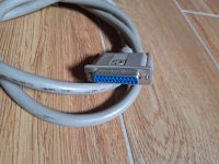
Unidentified Commodore cable
- Thread starter flaviosr
- Start date

Ruud
Veteran Member
A 25-pin to 9-pin serial cable? I only see one pin in the bottom row and I expected at least two, 7 = RTS and 8 = CTS. I don't know if Commodore Made/rebadged modems. If so, there is a possibility.
Regarding a video connector: vertical sync would be missing.
Regarding a video connector: vertical sync would be missing.
daver2
10k Member
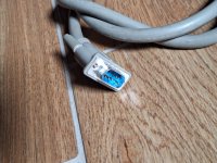
On the 'short' side of the DB9 I see 2 pins (if you zoom in).
Dave
Dave
CommodoreZ
Experienced Member
I think that's a video cable for an Amiga monitor? Question is which one.
That's not a DB-25 -- if I'm counting right, there are only 23 pins (which means it isn't quite a B-sized D subminiature shell).
But, the male DE-9 sure looks like what you might see outputting video for the 80-column mode on a 128.
You've got a real oddball there, that's for sure.
That's not a DB-25 -- if I'm counting right, there are only 23 pins (which means it isn't quite a B-sized D subminiature shell).
But, the male DE-9 sure looks like what you might see outputting video for the 80-column mode on a 128.
You've got a real oddball there, that's for sure.
daver2
10k Member
Good spot...
Dave
Dave
flaviosr
Experienced Member
I was wondering that the Amigas have RGB out on a DB23 male... perhaps these cables (I have two) are to be used with Amigas to be connected with old monitors with DB9 connectors...
I see there are a lot of Commodore monitor with DB9 female connectors... what do you think?
I see there are a lot of Commodore monitor with DB9 female connectors... what do you think?
Zippy Zapp
Experienced Member
Commodore RGB monitors had 3 main types of connectors on the back for inputs (not including LCA and Composite), depending on the manufacturer since they were mostly rebadged. They used a 9-Pin D-SUB both male and female and they used Round DIN cables on mostly the Philips 80 column RGB monitor that they relabeled as a 1084-P. I have a 1084-D and it uses the male 9-pin D-SUB on the back of the monitor. You can tone out the pins with a multimeter and see which monitor it matches up to by using the pinouts in most of the Commodore monitor manuals. But it probably is something like this:
Pin#. Description.
1 Ground. (Amiga RGB Pins 16-20)
2 Ground
3 Red <-> Amiga RGB Pin 3 (Digital TTL Pin 7)
4 Green <-> Amiga RGB Pin 4 (Digital TTL Pin 8)
5 Blue <-> Amiga RGB Pin 5 (Digital TTL Pin 9)
6 Intensity (CGA/TTL Only) <-> RGB N/C or Digital TTL Pin 6
7 Composite Sync (RGB Analog Only) Amiga RGB Pin 10
8 H Sync (CGA/TTL Only) (RGB N/C) Amiga Digital TTL Pin 11
9 V Sync (CGA/TTL Only). (RGB N/C) Amiga Digital TTL Pin 12
These are from my A500 and 1084 manuals. The RGB port on the Amiga is capable of both Digital TTL for 16 colors and Analog RGB for 4096 colors hence different pins on the RGB port depending on which monitor you are using. I did know a couple people that used actual TTL monitors never seeing the amazing colors that the Amiga could produce with Analog RGB.
If you compare the above to the cable then you will know exactly which it is and I would guess that most Commodore cables are ARGB and not TTL. But I seem to remember they did make a cable for TTL too.