• Please review our updated Terms and Rules here

VIC-20 Issues

CamiTheWitch

Member
Joined
Jul 11, 2022
Messages
12
Location
Denton, TX
So, I’m working on at least 3 VIC-20s at the moment, and all are in varying states of completely dead, and I’m hoping someone can help me find where to look.
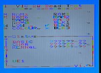
Number 1 boots but the white background is black and the keyboard input is garbled. It loads a cartridge but the not fully. The one time it worked well enough for me to check, I confirmed it can display white, so something is telling it to display black on boot.
Number 2 boots to a fully garbage screen, and after about 10 seconds the colors get funky and the screen loses sync. I’m assuming that’s a VIC problem, but I’d be thrilled if it isn’t.
Number 3 booted to a garbage screen once, but now black screens. I’ve checked the 65245 chips of units 2 and 3 in my TL566II+ and they all test as good (1 has regular 74LS245s and they aren’t socketed).
Any help is appreciated, thanks!
 
Hi Cami.

So I and others can help recommend the right troubleshooting steps, what tools/capabilities do you have? Multimeter, logic probe, oscilloscope, etc? Are you good at soldering and desoldering components?

For all 3 boards, first thing to check is that you have good VCC and VSS on all the major chips. Next check the reset line on the 6502, make sure its coming out of reset correctly.

For VIC#1: Garbled keyboard input would have me look first at the 6522 handling keyboard inputs. Displaying black instead of white could be any number of things. A bus contention on the data line is my first guess. And of course both 6522s sit on BD, as does the VIC.
For VIC#2: Changing after 10 seconds could be the CPU reset being released. Do you have a known-good VIC to swap with this one? The VIC-20 video circuitry is not complex, so there isn't a ton to test. What behavior do you get when a cartridge is in?
For VIC#3: Black screen would make me check that reset line immediately. I had one recently where a bad logic chip on the reset line prevented the system from booting.

There is a diagnostic cartridge out there. Since you're repairing 3 systems now, and maybe more later, it could be worth it to pick up.

You can find manuals and schematics on the Zimmers FTP:
 
"and all are in varying states of completely dead"

So, from your description none of them are "completely dead", right? They all seem to be at some state of life, but need troubleshooting.

I think there are plenty of folks here who can help. I will be interested to follow along and see what happens.

Seaken
 
I have a decent number of tools but I’m not sure how to use them in this situation. Specifically for tools I have an oscilloscope, logic analyzer, logic probe, multimeter, EEPROM programmer, and soldering iron at my disposal. Most of them I got cheap when I worked at an electronics store and never really learned how to use them to their fullest.

I’ve written a test cartridge to ROM and stuck it in the machine. The last two still have a black screen, and the first one claims nothing is wrong. I’ve swapped the VIC chip and nothing changed, so I’m guessing it’s a logic chip somewhere that’s malfunctioning. I have another board that says the color RAM is bad, but after swapping the RAM and 4066 nothing changes, and if I let it run long enough the screen starts to get garbled. (I attached a photo for this one.) These are such simple little computers, it’s kinda discouraging to me when I have so much trouble even determining where the problem could be lol. I think for now I’m gonna focus on the two that have video output, and save the black screen ones for later.
 

Attachments

  • E7D5E6EE-9F1C-4A6E-8EBC-C94BEC588188.jpeg
    E7D5E6EE-9F1C-4A6E-8EBC-C94BEC588188.jpeg
    810.8 KB · Views: 15
Great! You should have all the tools and know-how to get these machines back to working order. Don't be discouraged! You will get them all working, or at least know why they don't.

Like you said, I'll ignore the black screen VICs for now so we can focus on the ones semi-working.

First thing to do then is get the oscilloscope out and start checking the lines, see which line has the problem. From there you can see what sits on that line and narrow down the issue.

The ol' wiki has your pinouts for the 6502 here: https://en.wikipedia.org/wiki/MOS_Technology_6502#/media/File:MOS6502.svg

I'd verify the 5V on pin 8 and ground lines at pins 1 and 21 look good. Check the clock input on pin 37 and both clock outputs at pins 3 and 39. To check the reset line on pin 40, hook up your o-scope probe and THEN apply power. It'll start low for several seconds then jump high. The VIC-20 is really slow to come out of reset on boot. After that I'd be checking address and data lines to see if anything has an odd looking waveform on it. Anything stuck in the middle (like 2.5v, not good TTL low or high), or signals that seem to try to transition from low to high but fail to do so (like 5V drops to 3.5V then goes back up to 5V).

if I let it run long enough the screen starts to get garbled.
So many times I've seen this and its bad system RAM (not the video RAM, though its worth checking). So I'd start there. Sometimes you can tell by the characters or colors which bit is stuck, helps narrow down which RAM chip is bad. Did you try touching the chips, see if any get really hot? Other than the VIC of course, it always runs hot.

It might ease your mind to do a bit of reading. This Tynemouth blog post is a great primer: http://blog.tynemouthsoftware.co.uk/2019/09/how-the-vic20-works.html
And I found this video from Adrian Black, where he fixed up two VIC-20s. Any video he posts is worth watching, great guy and a great approach to fixing these machines. Might get your head in the right space for how to approach the problem.

Let us know what you find!
 
If it is colour (chroma) that is the problem - I would start at the VIC chip itself (with your oscilloscope) and obtain some data points first.

Check the clocks on the VIC chip at pins 38 and 39. Are they the correct frequency for your machine and are the clock signals stable as the fault materialises or changes? If they are, the problem is not the clock to the VIC chip.

Next, look at the VIC chip chroma (colour) output on pin 2. Note that this appears to be fed via a low-valued capacitor. Is the chroma pin changing (on your oscilloscope) with a stable picture as the fault changes? If so, we have at least found something we can work with. I would also check the capacitor...

EDIT: Depending upon the variant of VIC-20 you have, there may be two (2) capacitors on the chroma output pin from the VIC chip - one in series and the other to ground.

If you have already swapped the VIC chip, then we can probably rule out the silicon. I would check the power pins of the VIC chip (20=GND and 40=VCC) for the correct DC value, being stable and not a lot of noise (again, using your oscilloscope). DC coupled for the actual voltage measurement and AC coupled for the noise measurement.

After that, we work our way backwards.

The 2114 RAM is notorious for failing - as are the 245 buffers used for the address and data bus. But I wouldn't consider changing them unless we had some definitive reason to do that.

I would be tempted to use the oscilloscope on the data lines of the colour RAM (with a static picture on the screen) and, again, look for changes in the signals over time. Basically, to see what is going on.

The first part of diagnosing a fault is checking that obvious signals should be present and stable e.g. power rails, clocks, etc.

The second part of diagnosing a fault is to obtain some data points.

Dave
 
Last edited:
Since you have 3 VIC-20, I would swap the VIC chips and see if it something changes. That way you could get some info about the three VIC chips;

- if it doesn't change anything in the VIC-20 with the color issue (screenshot above) you will know the VIC isn't the culprit;
- if you get a black screen, you know that probably the VIC of the other VIC-20 is dead;
- if it solves, you know that the VIC from the VIC-20 with the color issue is bad.
 
Back
Top