• Please review our updated Terms and Rules here

VT100 Video Output Problem

rjarratt

Experienced Member
Joined
Mar 30, 2008
Messages
128
Location
UK
I have been restoring a VT100. I have replaced one of the RAM chips and the sender UART for the keyboard and the main board seems to work, except for the video output. I think the bad video output may be affecting the video driver board, so I have removed it for now. I am using the external video connector to drive an LCD screen and a little video converter. I have tested this setup with a known working VT102 to make sure it works, the output isn't displayed quite right, with a bit of clipping, but it is recognisable.

However, when I use this setup with the VT100 all I can see is what I believe to be the cursor flashing, but for the full height of the screen. If I type characters the cursor moves across the screen but I don't see any output relating to the characters. If I press the SETUP key I just get a completely black screen. I do see something that looks like a test pattern immediately after powering on, but it is random vertical bars, whereas the VT102 displays a large block of white.

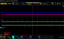
I have checked that the DMA is transferring the correct data from the screen RAM using a logic analyser and it is getting to the character generator ROM. And I can see bits coming from the character generator ROM, so even if the character generator ROM was bad I would think I would see something, even if it was garbage. The fact that something does get displayed would suggest that the DC012 is working, and I can see that its other outputs seem valid, like HOLD REQ H etc. If there was anything else between the DC012 and the actual composite output that wasn't working it would seem unlikely to manifest itself like this, although I confess I am not sure I understand the circuit between the DC012 and the actual composite output, so I could be wrong.

I wonder if anyone has any suggestions for what to look at?

Thanks
 
Just been looking at the VT100 a bit more. I noticed E10 (VIDEO SHIFT REGISTER) is very hot, too hot to touch. This is in the path to the DC012, so I wonder if it might be bad and need replacing. Anyone know if this chip is likely to get that hot? I realise it is a 74S299, and I believe the S series has higher power dissipation, so perhaps this is expected?
 
Last edited:
If you have a scope, trigger it on pin 12 (Dot Clk) and observe pin 17 (Video Out) to see if there is actually a bit stream being generated. You could also use your logic analyzer. Similarly, have a look at pin 19 (VSR Load) to see if the parallel data is being loaded into the shift register.

If the clock and load signals are present, but nothing at the video out pin, the shift register is likely bad. You can get a replacement from Jameco for $1.19:
https://www.jameco.com/z/SN74S299N-...-Shift-and-Storage-Register-20-pin_48741.html

If you see the data on the Video Out signal, the next place to check would be pins 18 and 19 of the Video Controller (E5 - DC012) which are the two signals that are mixed with the sync signals to generate the composite video signal.

I would not expect the shift register to be that hot... too hot to touch.

Good Luck! Jon.
 
Thanks Jon. I have sort of done some of the things you suggest but not exactly in the way you suggest, so will try again to see if I can be more certain about where the fault is. Although I am pretty sure it must be the 74S299 as it gets so hot, the one on my VT102 is nothing like as hot. In the meantime I have already ordered some 74S299 chips, ready to replace it if I confirm the fault is there. Unfortunately, it will be a little while before I get the next opportunity to work on it.

Thanks

Rob
 
I replaced the 74S299 with a new one but the fault did not go away and the new one also gets very hot. I have checked the inputs to the shift register. I get the following signals:
1711203153550.png
The blue signal is BV4 DOT CLK and the yellow signal is BV4 VSR LOAD H. By comparison the same signals on a working VT102 look as follows:
1711203221028.png
The signals are spikier on the bad machine, but look OK otherwise and would not appear to explain why the chip gets hot. I suppose it would get hot if the outputs were being loaded too much, which could only happen I think if the DC012 chip was bad. However, the DC012 itself does not get hot, so this seems unlikely to be the cause of the shift register getting hot.

I have also used my logic analyser to see what data is getting loaded into the shift register in the first place. I would expect it to match the character generator ROM patterns in the Technical Manual (p128 of the PDF). But with my working VT102 I could not capture anything that matches what I see in the manual so I am not sure if I was doing it right. My logic analyser also has fairly simple triggering and I couldn't get it to capture only non-zero data being loaded, so it is quite hard to see what is going on. So I didn't bother to try seeing what actual data the shift register is getting on the faulty VT100. With the scope though I can see that there is some data coming out of the shift register and it changes if I press the SETUP key on the keyboard.

I do see output on the DC012 output, but it is not the same as the output on the VT102. However, not knowing if the inputs to the shift register are valid or not makes it hard to be sure if the DC012 output is correct. Given that the shift register gets so hot though, is it reasonable to suspect the DC012?

If I could find a way to capture the inputs to the shift register better that would help a lot, but my logic analyser doesn't seem to be up to the task because it needs to trigger on the rising edge of the clock AND on the S1 input being high AND the inputs not being zero.
 
Digital ICs draw excessive current when switching, not when sitting at a sepecific logic level 1 or 0. The static fan-out load is a factor for the current draw of an output pin, but the switching is what really draws all the current.
The shift register inputs, as you captured in the first photo [trace 2], are definitely not good. excessive ringing and what appears to be very slow rise and fall times.
Check your probe setup for calibrated probe, proper ground and short wires. If indeed that is the signal seen there, I'd investigate that first.
-Alon.
 
Thanks Alon, but I used the same probes and same grounds in both cases. I think I have noticed generally spikier signals on the faulty machine than on the good one. I checked the PSU output capacitors and they seemed OK, but maybe I should check again?
 
Thanks Alon, but I used the same probes and same grounds in both cases. I think I have noticed generally spikier signals on the faulty machine than on the good one. I checked the PSU output capacitors and they seemed OK, but maybe I should check again?

The power supply rail should be checked for sanity but has nothing to do with these spikes, as they are transient spikes generated somewhere in the working machine, and not introduced to the machine by the supply.
You mentioned "spikier signals" on the faulty machine in general, so the issue is not likely due to a specific IC causing trouble.
Excessive ringing as you have captured can be caused by many issues, including too-long wires (both supply/ground wires and signals), signals that should be terminated but are not, an IC or a board missing a proper ground but somehow closing a ground through an unintentional long and meandering conduction path, and I'm sure a dozen more reasons that I can't think of right now.
Forum members with more experience in such debugs may correct or add to my list of possible issues.
-Alon.
 
Finding any of those sounds difficult, but I guess I will need to check them. There is a cap across Vcc-Gnd on the shift register which I can check.
 
Looking at the schematic, the Feb82 printset has an inductor (L8) on the DOT CLK H output from the DC011, it is the output of L8 which drives the CLK input of the shift register (the blue trace in the scope screenshots above). However, my board does not have L8, and I see that the Mar80 version of the printset does not have it. I wonder if L8 was added to prevent these spikes? Is it possible that the traces I am seeing are actually to be expected?
 
I wouldn't get too excited about the spikes and ringing and overshoot that you see on the waveform. Or the digital noise in the LSB's either

Generally it is likely the scope's probes are not properly compensated for the scope's input capacitance. The recordings are also affected by where the earth's of the scope probes are connected because of common impedances in the earth tracks.

You see this sort of thing all the time with digital scope recordings (like Rigol scopes and other digital scopes) used on computer logic circuits.

If I saw this sort of thing with my 400MHz analog scope with a known good compensated x10 probe (that was specifically designed for it and had the compensation capacitors capacitor adjusted on a Tek fast rise square wave generator, like Tek's PG506) then I might be worried that the overshoot pulses are really there, otherwise, with a common digital scope setup, I would pay no attention to them at all , because most likely they are an artifact.

( It pays to do all recordings with a properly compensated x10 probe where the input capacitance is less than 30pF normally, rather than a x1 probe where it applies more than 150 to to 200pF to the circuit point you are testing which can cause problems both in giving displayed waveforms that are not there when the probe is not connected and delaying pulses)

If you had a fast rise Tek calibration generator like the PG506, and/or its associated Tunnel diode pulser, which produces a perfect Heaviside step function, you could check this for sure, but not everybody has this gear on hand.
 
Had my VT100 out so checked mine. E10 does not get that warm on first board I tried. When I put in one with AVO that chip when finger was over die was toasty but not hot enough to worry about burning finger.

If you can trigger off video/vsync you can see a clear pattern difference between setup and blank screen.

Trace 1 is BNC video out. Trace 2 is pin 7, Trace 3 is pin 17. Trigger is set to TV line 7. You may be able to trigger off vsync with pulse width trigger if you don't have TV/Video.
This is blank screen with blinking cursor. The video out positive pulses goes on and off with the cursor blinking.

RigolDS54.png

And this is setup screen. I don't know why we see activity that doesn't make it to the video.
RigolDS53.png


If you socketed E10 you could try lifting pins and see what ones cause the heating. My clock looks like your squarewave one with less undershoot.
You could cut w1 to disable the chargen and pull E9 if present. That would make data to shift register always 1.

If your getting repeated cursor down the screen that sounds like line addressing problem. May be a good start for troubleshooting.
Setup then 0 will put up some character patterns on screen while it does the test test. Your vertical bars sound like its repeating the first line for the entire screen.

Couple things you can try. Set reverse video mode. Setup A/B, 4 right arrows, toogle 1/0. Toggle should switch between white and black screen.

If you have advanced video option
Esc(0x should be vertical bar with pixel set at top. More x should be more bars. If you get vertical line its line counting problem.
Esc[7m switch to reverse video mode. Characters you type will be in reverse video.
 

Attachments

  • RigolDS4.png
    RigolDS4.png
    93.7 KB · Views: 0
Thanks for the suggestions, I will go through them in the coming days. I did think that it could be repeating the first line over and over, but I don't think that is the case, because when I type letters in local mode the full-height cursor moves across the screen, but no letters appear. It could be that the character ROMs are bad, but I would expect to see garbage in that case, unless they are so bad that they just return zeroes. This is why I was trying to capture the data being loaded into the shift register with my logic analyser. Unfortunately my logic analyser doesn't seem to have enough capability to do this, but I may try to look at this again to see if I can capture data on the working VT102 first so I can confirm that I know what I am looking at is correct. I suppose I could remove the ROMs and check them with a programmer, but they are not socketed which is a shame, that will be a last resort.
 
I hadn't considered that it would be the first row of pixels, only the first row of characters. When I use characters that have pixels at the top then I do see them repeated all the way down the screen. What is curious though is that it isn't just characters like the vertical bar, which has a pixel in the very top row, but also characters like # and parentheses, which have pixels in the second row. So it can't be repeating just the very first row of pixels. I am going to experiment with other characters and see which ones display anything, to see how many rows of pixels it displays.
 
I have been looking at this further and comparing my faulty VT100 with a working VT102. I suspect that the DC012 chip may be faulty in that the scan count outputs (SC0-SC3) seem to be only ever all zeroes or all ones. On the working VT102 I can see these outputs count up from 0-8 then F then back to 0 again. But on the VT100 they seem to be almost always 0 and occasionally F. If there was a fault pulling the lines low then the output could never be F. So this makes me think that either the DC012 is getting some invalid inputs that are causing it not to update the counter, or somehow the counter is either not updating, not reaching the output pins or some outputs are shorted together. There are no externally measurable shorts between the SC0-3 outputs of the DC012. According to the Technical Manual the counter is updated on the HORIZ BLANK signal and that looks fine on the input to the DC012, it pulses every 63us, just like it shows in the TM. One thing that can influence the scan count is smooth scrolling, but I have traced the firmware to see if it thinks it is trying to do smooth scrolling, but it doesn't seem so.

It seems to me that this can only mean that the DC012 is faulty. Would that seem reasonable? Are there any other reasons why it might not output the scan count?

If the DC012 is faulty then of course I would like to try to replace it. I have found a few "sources" on the web for the DC012, none in the UK of course. Would anyone care to suggest a reliable supplier that would sell to an individual? My other alternative is to buy a whole board on ebay, there are a few for sale, shipping to the UK is expensive though!
 
I have a few DC12 from a former DEC Repaircenter, so the are genuine for sure
I am based in Austria
You can have two for free, not worth to send the few euros...

But I am not going to fill any customs forms - not sure if this will go through ?
I would flatten the pins, so they fit in an normal envelope
PM me if you want them
VT100 DC12.jpg
 
Well @bigfix sent me two DC012s. I took the old one out, soldered in a socket and installed one of the "new" chips. As you can see below, the external video now works! :) I now need to reassemble the monitor board and see if the flyback is OK, but I have a strong suspicion that it has failed.

However, I noticed that the video shift register (E7) still gets almost too hot to touch (despite replacing it with a new one) and the DC012 is also quite warm. I wonder if this is what caused the original DC012 to fail? Does anyone have any ideas why these chips might get so hot despite now appearing to work OK?

Thanks

Rob

VT100 After DC012 Replacement-1.jpg
 
Logic IC's that are doing significant high speed counting do get quite hot. This can include multi-stage counter IC's and shift register IC's. It might be normal for that IC to run that hot under its current operating conditions. Likely you have checked the power supply voltage is normal. It is pretty unlikely that any of the IC's outputs are significantly overloaded, and causing additional heating effects that way, because the IC is working in the application.
 
Back
Top