• Please review our updated Terms and Rules here

VT100 Video Output Problem

Logic IC's that are doing significant high speed counting do get quite hot. This can include multi-stage counter IC's and shift register IC's. It might be normal for that IC to run that hot under its current operating conditions. Likely you have checked the power supply voltage is normal. It is pretty unlikely that any of the IC's outputs are significantly overloaded, and causing additional heating effects that way, because the IC is working in the application.
I did wonder if it might be normal, but I checked on a working VT102 and the same chip does not get anything like as hot. I can smell the heat and it is too hot to touch. I have been trying to use my multimeter to measure the temperature as it has a temperature function. I don't know if I am doing it correctly, but at one point I seemed to get a temperature of 60 degrees Celsius. Surely this thing is too hot?
 
I did wonder if it might be normal, but I checked on a working VT102 and the same chip does not get anything like as hot. I can smell the heat and it is too hot to touch. I have been trying to use my multimeter to measure the temperature as it has a temperature function. I don't know if I am doing it correctly, but at one point I seemed to get a temperature of 60 degrees Celsius. Surely this thing is too hot?
Well, I would measure the min/max voltage at each and every pin, preferably dynamically on a scope.
Should never be much above 5.5V (assuming 5V VCC) nor below -0.5V.
Severe overshoot/undershoot could cause excessive power dissipation.

If the chip is in a socket it might be possible to lift the VCC pin and insert a current probe inline to see if current is within reason.
 
As noted in my last reply, the same chip in a VT102 does not get anything like as hot.
I had noticed the same thing between my VT100 boards. Its possible that some chips were more efficient. Datasheet says 140mA typ 225 max so 0.7W typ 1.12W max. Could power it up on the bench and see if it gets as hot.
 
I just measured 5.1V on Vcc to the chip. This chip is a recent replacement for the original one because I thought it might be faulty, so it shouldn't be a bad part if both of them get hot.

A few posts back there was discussion about the under/overshoot because there is some of that going on. However, it seemed that the conclusion was it could be more of an artefact of my low-end scope or poor measuring technique, see this post and the subsequent discussion. If it really is spikes and ringing I am not really sure where to begin.

You should be able to get a decent measurement and visuals even from a cheap-o-scope.
Make sure you are using a 1:10 probe and that it is calibrated, calibrate using a clean square wave source or your scope's "probe comp" output if it has one.
When connecting the probe's ground to your equipment, it should be using the shortest wire/path possible and as close as possible to the signal you are measuring.
Ideally, locate the specific IC's ground pin and attach the ground of the probe to that, or to a component's ground pin very close to it, using one of those tiny hook clips.
Any signal you see that is not a constant logic 0 or logic 1 raises the IC's current consumption - the rise times, fall times, and all sorts of bounces not near the 0V or 5V levels.
-Alon.
 
Thanks Alon. I am using a 1:10 probe. I am pretty confident that the probe I was using was calibrated using the scope output, and I was using the same probe on the good VT102 as the bad VT100. However, I do know that I would not have connected the probe ground wire to the chip's ground pin. So, I will verify that the probe is set up correctly, connect the probe ground wire correctly and then double check.
 
That might be a good idea, but I would prefer to get to the cause of the excessive heat really (if I can!)
 
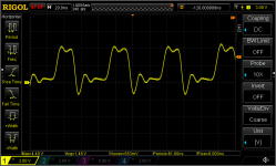
I checked my probe against the scope's calibration output and used a test clip so that I could connect the probe ground wire directly to the chip's ground pin. This is what I got:

1712851471086.png

So I think the under/overshoot is genuine. How do I go about finding the cause?
 
I checked my probe against the scope's calibration output and used a test clip so that I could connect the probe ground wire directly to the chip's ground pin.
Perhaps I'm unclear what you're doing there, but to calibrate the a probe you need to connect the probe's input clip and ground clip to the calibration output waveform and ground contacts, and make sure you're getting a clean square wave. If you're not, use a non-metallic tool to turn the adjustment dial on the probe body until the square wave is clean.

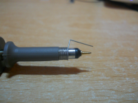
Once you've done that, you can then move the probe back to the signal on your board that you want to check. For best results, if you can, use the shortest wire possible between the probe ground and the board ground. Many probes come with a set of little springs that you can attach to the ground just behind the probe tip to make that as short as possible, if you have a ground near enough to the signal that it can reach. But a test clip connected to the same ground band to which the alligator clip attaches should also be ok at these relatively low frequencies.

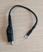
I don't have a picture of the test clip attachments I made for my probes, but they were based on the alligator clip attachment below; I bought some more of those, cut off the alligator clips, and soldered on test clips instead.

This EE Stack Exchange answer shows how to use the ground spring and gives some examples of how waveforms can differ between using that and a longer ground lead.
 

Attachments

  • 1712856287007.png
    1712856287007.png
    1.4 MB · Views: 4
  • 1712856378435.png
    1712856378435.png
    2.7 MB · Views: 4
Last edited:
Yes I calibrated the probe by connecting it to the two contacts on the scope designed for this purpose. I used a plastic tool to turn the dial until the square wave was perfectly square. Only then did I try to measure the signal on the chip. I tried to keep the length of the ground as short as I could, but I needed to use a DIP test clip as the ground wire on the probe is like your second picture and I was worried the alligator clip is a bit big and could short the next pin to ground. I don't have a ground spring or an alternative way of connecting ground. Using the test clip adds about 4cm to the ground wire on top of the wire actually connected to the probe.

Given that using the same probe and scope I didn't see these over/undershoots on the VT102 (where the 74S299 stays cool) I am fairly confident that what I am seeing is real.
 
  • Like
Reactions: cjs
Hello again. I haven't been able to look at the VT100 again until today. I decided to try a regular PC PSU supplying the VT100 video board, just to exclude any possibility that the VT100 PSU might be causing any issues with the over/undershoots. I know I was told the PSU would not be the problem and indeed the signal looked exactly the same as it did in my post of 11th April. So, as was suggested to me a while back, the problem is on the video board itself.

I am not really sure where to start with diagnosing this now. Does anyone have any suggestions for how best to debug this?
 
Back
Top