• Please review our updated Terms and Rules here

VT101 monitor restoration

jmdhuse

Experienced Member
Joined
Apr 30, 2022
Messages
145
Location
USA - Arizona
Hello All,

Not too long ago I picked up a VT101 monitor for $100... it was unknown if it worked, but if it didn't I wasn't out too much. It did not have a keyboard, so my first step in getting it together was to build an interface that would convert a PS/2 keyboard to the VT100 keyboard interface. I have this working, although the firmware still needs work.

The monitor is the real question - I can use the brightness, height, and vertical linearity pots to adjust the display position, but on the whole it is so out focus you can't make out anything on the screen. When I press the SETUP key repeatedly, I can see something changing at the top and bottom of the screen, but it is not readable. I'm pretty confident that the logic board is operational because I have verified that communications works properly and I can hook an external monitor to the video out BNC connector and see a correct display.

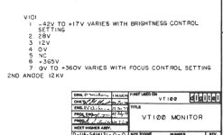
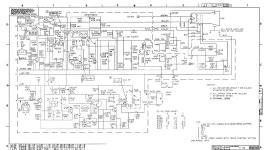
The power supply generates all the proper voltages, although the board near the chain of Zener diodes that creates -23V for the options NVRAM shows some heat discoloration. The main symptoms I have discovered are 1) the focus pot has no visible effect on the screen, and 2) the voltages at the tube are higher than the notes on the schematic indicate. The CRT board I have matches the schematic in the VT100 print set (MP00633), which indicate that the red connection to the tube should be +365V and the range for the blue connection (focus) should be 0V to +360V. On my board, the red connection voltage is +413V and the focus range is 0V to +402V. Are these higher than expected voltages a problem? I see that they are generated by secondary windings on the flyback transformer, so it seems strange that they are so different than what is spec'd.

I don't have much experience with CRTs, so I'm interested in any help or hints on how to go about this.

Thanks and cheers, Jon.
 
Could help probably, if you posted a schematic and marked on it the voltages you have measured around the CRT area, otherwise the crystal ball is too foggy to make an intelligent remark.

I'm not sure what the Red Connection is (unless it is a woman named Natasha). It may be the CRT's A1 anode, if that is too high it can cause the brightness control to go out of range. Does the brightness control extinguish the beam completely ? Though depending on the gun it might put the focus out of range.

For a CRT to come into focus the other gun elements have to have correct (or close to voltages). And the CRT has to be non-gassy.

Could you also post a picture of what you are seeing on the screen ?

Sometimes, severe loss of the HF components of the video signal can be mistaken by some to be an out of focus effect. Can you get the scanning lines to come into focus with the control ? (regardless of what the video looks like). This is where a photo is handy.
 
Jon,
Nice work that keyboard conversion.
Beware if you ever find a similar looking keyboard but from C.itoh version, looks completely the same but does not work on a VT100.

Check on pin 7 if focus R477 will make the full range 0V- +360V
Then check those capacitors round that HV-Transformer.

From cpu-board the horizontal line signal enters the E1(NE555) through that circuit the Horizontal signal drives the HV-transformer to establish all voltage CRT.
Check Source voltage 144V.
Then with L403 see if you can adjust back to +365V on pin 6 CRT.
Take right ground as reference , Pin 1 ,Horizontal GND,PCB Board.
 

Attachments

  • VT100-CRT-sch-web2.jpg
    VT100-CRT-sch-web2.jpg
    44.9 KB · Views: 5
  • VT100-CRT-sch-web1.jpg
    VT100-CRT-sch-web1.jpg
    406.2 KB · Views: 5
  • VT100-CRT-sch-web3.jpg
    VT100-CRT-sch-web3.jpg
    199.1 KB · Views: 5
Thanks for adding the schematic... I will try adjusting the inductor and see what happens. Here is a photo of what the screen looks like with the brightness pot turned up enough so that the scan lines are visible. There seems to be a kind of scan "overlap" on the left side of the tube.

screen.jpg
 
Jon,
Nice work that keyboard conversion.
Beware if you ever find a similar looking keyboard but from C.itoh version, looks completely the same but does not work on a VT100.

Check on pin 7 if focus R477 will make the full range 0V- +360V
Then check those capacitors round that HV-Transformer.

From cpu-board the horizontal line signal enters the E1(NE555) through that circuit the Horizontal signal drives the HV-transformer to establish all voltage CRT.
Check Source voltage 144V.
Then with L403 see if you can adjust back to +365V on pin 6 CRT.
Take right ground as reference , Pin 1 ,Horizontal GND,PCB Board.
I've ordered some non-metallic tools so I can adjust the inductor slug... we'll see.
 
Update - when I went to adjust the inductor slug, I found it was broken, and the schematic does not give meaningful information about the inductor's specs. But, luckily, I did find on Ebay a video board for sale. I purchased it, installed it, and the monitor now works fine. Yay! I'd still like to figure out how to repair the original video board, but it's not on the top of my project list.
 
The overlap that you see (Broad white vertical band on the left and tilted vertical retrace lines over the screen) are because there is no vertical and no horizontal blanking of the beam during both vertical flyback and horizontal flyback. These go away when a correct video signal applied to the CRT, as it cuts of the beam during H an V retrace times. This set does not have internal retrace blanking (as some VDU's do) so it relies on the video signal to do it.

The finer dark vertical lines on the left, often represent small oscillations on the damped H yoke coil current immediately after H flyback.

I'm not sure what slug you were referring to, perhaps the width inductor L403, this will adjust the scan with. The main reason these slugs fracture is because people use a metal tool in them rather than a plastic one, so its a good thing you are getting the plastic tools. Once the slug is split longitudinally then any attempt to rotate it causes it to expand and the sharp fracture edges lock it in the threads. (There is a special way to remove these slugs, if that happens, and it doesn't involve trying to drill or grind them out)

The beam focus you had on the raster scan looked reasonable, possibly the out of focus effect you had was a loss of HF response in the video signal and a problem in the original board's video amp. Maybe academic now that you have replaced the whole board.
Yes, I am referring to L403. A couple of questions - can those slugs be purchased as a stand-alone item? Also, do you have any idea about how to find the spec for the inductor? Can I take it off the board and just measure it with an LCR meter?
 
Yes, you can just measure the inductance with a meter, since it is in a series circuit with the yoke, just disconnect the yoke and connect the meter across the inductor. The other series inductor L402 is a magnetically saturable linearity coil and that is a hard part to replace. The exact field intensity & position of the magnet with respect to the coil axis has a significant effect on the H scan linearity. Without that coil, the raster scan would be larger in amplitude and stretched on the Left hand side.

Often the slugs in Width coils, were common parts in many coils, not often sold separately, sometimes, If you measure the diameter and thread pitch, likely you'd find one on ebay. Most Ferrites work for the application.

In an H scan circuit, the rate of rise in amps/second, which is typically around a frightening 50,000 Amps per second, in the H coils is set by the power supply voltage divided by the total inductance, including the yoke coils, the width inductor and the linearity inductor. The H output transistor acts as a saturated switch. The width coil, adding inductance because it is in series, decreases the H scan amplitude because it lowers the rate of increase of current with the time.

Typically the peak H deflection current in a VDU of this size rises to around 1.5 to 2A because despite the large rate of increase of current with time, the output transistor is only carrying current for about 32uS. 50,000 x 32 E-6 = 1.6 Amps by the time the beam has got to the R hand side of the raster. At this point the transistor is actively driven into cut-off, flyback begins, the magnetic fields of the yoke and output transformer begin to collapse (tuned by the primary tuning capacitor) A peak flyback voltage appears on the transistor's collector. This peak is transformed up and rectified to create the CRT's EHT. After that half cycle of un-damped flyback oscillation, the magnetic field is now reversed in the yoke & transformer, the CRT beam is on the left hand side, with now about -1.5 Amps yoke current as damper diode conducts and returns the magnetic field energy back to the power supply to scan the left side of the raster. This idea, called energy recovery scanning, was invented before WW2. Despite the fact the peak currents are high inside the Yoke circuit at +/- 1.5A, the average current consumption, from the power supply is low, due to the returned energy.

Therefore as you unscrew the Ferrite slug from the width coil, its inductance drops and the scan width increases. One important feature of the Width coil, the Lin coil and the H yoke coils is that they all have a relatively low DC resistance. You cannot replace the width coil with another coil, just because it has the same inductance, it must have the same or a lower DC resistance as the original coil. Likewise the S correction capacitor C441 is a special part with a very low ESR. Resistance in this part of the circuit, due to the high range currents, generates heat and it also degrades the scan linearity with compression of the Right side of the raster scan. Some people think these capacitors are standard electrolytics , they are not, their ESR is usually less than 0.15 Ohms. If they require a replacement it must be with a film capacitor, preferably with a higher voltage rating like 160V or 250V.
 
Last edited:
Back
Top