• Please review our updated Terms and Rules here

VT420 troubleshooting

PG31

Veteran Member
Joined
May 31, 2011
Messages
509
Location
Sefton, Meresyside, England
Does anybody have experience troubleshooting a VT420? I have one that does not display on screen when powered up but makes a continuous clicking sound (switch mode startup?). I have the service manual but I have not been able to find a circuit diagram. I cannot see the heaters glowing on the CRT and no beep or LED's on keyboard. Thanks.
 
Does anybody have experience troubleshooting a VT420? I have one that does not display on screen when powered up but makes a continuous clicking sound (switch mode startup?). I have the service manual but I have not been able to find a circuit diagram. I cannot see the heaters glowing on the CRT and no beep or LED's on keyboard. Thanks.

Noot got any info, but does sound like the PSU. Might be wirth asking on the DEC Legacy list..
 
Circuit diagram for the 420 is not available on line (i've looked)

I am trying to get mine working, but its very dim and all squashed up. Need a HV probe for my Fluke to see if the flyback is putting out the correct voltage (or if the tube is on its way out), and annoyingly I cannot find mine anywhere.

May have some spares from my messing about. Will let you know.
 
Thanks both, I have also asked on a couple of DEC Facebook groups. No joy yet. @Gary, you will find in the service guide a description of each potentiometer function on the circuit board. You may be able to get it a little brighter with the subcontrast pot. I've always used non conductive tools when adjusting any pots or inductors on a monitor/crt board.
 
It’s completely antidotal and may be way off track but two things I know from some time spent fixing both TV sets and later switching supplies. From what you describe it sounds like the switching supply is coming up and instantly shutting down like its supposed to do in the event of a failure anywhere else in the terminal.
From the back of the set on the right hand side is the switching supply. Do not think you have issues with the hot side of the supply because of what you say so I would look at the output of the supply just past the switching transformer and check for short across one of the two DC outputs, maybe something like a shorted capacitor right in that power supply block. Another thing to look at is to check the Horizontal output transistor located over on the heat sink by the flyback and the damper diode next to the flyback. Also use to see a lot of failures on small displays of thinks like the yoke on the tube where you were able to pull the four pin plug for the yoke and the set will come back to life if its bad but beware there will be no deflection and you can quickly damage the tube this way.
Beware!! That display has a section of the PC card that’s at line potential. Be extremely careful where you touch or ground to and do not connect any test equipment to the HOT part of the chassis. This can kill you! Also remember that the display develops around 15 kV from the flyback up thru that red wire to the tube so once you get it working don’t mess around with the red wire or the flyback. Unlike the hot or primary side of the switching supply it won’t kill you but can easily knock you on your ass.
 
Disclaimer: I am not telling you to do this unless you have an understanding of working with high voltage analog circuits, and all of the relevant safety protocols and procedures involved. The display has lethal voltages involved and once the cover is removed they are exposed. The protective shielding will not prevent you or protect you from coming in contact with lethal voltages that are involved.

Looked at the schematic and also one of my 420 and see where if you look by the +5 volt regulated pot you will see three small capacitors, C908 is the +12 volt feed, C910 is the +5 volt feed and C913 is the -12 volt feed.
With the display turned off check the DC resistance to ground on each power bus. It should be at least 50 or so Ohms to ground on the +12 and +5 volt bus with around 500 Ohms on the -12 volt bus. You can use the ground strap on the tube for a meter ground.
There are a handful of electrolytic around the power supply and if any short that will shut down the power supply after a couple cycles.
If you can get the board out check the resistance to ground across C619, that’s the + 41 volt source for the Horizontal output transistor. If there is a short or low reading you may have a blown horizontal output transistor.
If all that’s good you may want to look at C804 the big electrolytic on the hot side of the power supply along with C805 and C808 being if they are open they can keep the power supply from starting. Just remember they are on the HOT side of the chassis and all connections to the AC mains must be removed before doing any of this.

I do apologies if you do have a background and training in this in terms of overstating the safety aspects but this is right up there with disassembling and working on switching supplies and if you have never received any training on this it is a dangerous thing.
 
Thanks wupf and Qbus, great we now have a diagram:D. I have some experience fixing monitors (Zentec, Redifon, Newbury Data and Wyse mainly), albeit it 25 years ago. I will in this instance make all the "cold" component checks first. I have a capacitance meter, multimeter and scope.
 
Thanks wupf and Qbus, great we now have a diagram:D. I have some experience fixing monitors (Zentec, Redifon, Newbury Data and Wyse mainly), albeit it 25 years ago. I will in this instance make all the "cold" component checks first. I have a capacitance meter, multimeter and scope.

Sorry I don't have a name. I am close and think I have a working VT420 so let me know if you fail.

Dec Legacy is NOT a facebook group its a groups.io list. Most members avoid facebook like the plague but do exhibit their systems in Windermere from time to time.


https://wickensonline.co.uk/declegacy/


https://groups.io/g/declegacy
 
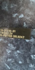
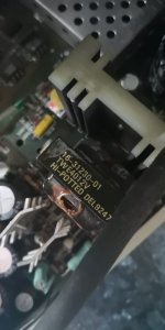
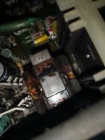
Hi Dave, I'm Paul.:) I've removed and cleaned the circuit board. I found the top of transformer T802 inside the terminal. Not 100% sure if this transformer has blew. I'll remove it from PCB at the weekend and check for open circuits and shorts. I took some photos but I'm having problems uploading them due to size being too large.
 
Yep. That is the schematic I scanned. I posted it to cctalk last year, but forgot to cc Al Kossow. So it didn't end up bitsavers apparently. Got to fix that. It was an ex DEC field engineer that gave it to me. http://storage.datormuseum.se/u/96935524/Datormusuem/DEC/VT420-engineering-drawings.pdf

My experience is that it is very unlikely that transformer goes bad. With the exception of one FBT I had no transformer going bad at all. When the PSU ticks it is very likely that it tries to start up but discover some kind of situation that causes it to turn off immediately. Over current situation is in my experience most common source. That could be the load itself or faulty output rectifiers.

Check all the output rectifiers. Disconnect the load and use a proper dummy load. Some PSU don't like to have uneven load. Depending on how the regulation is done uneven load could cause crowbar circuit to trap and then there is over current situation as a result. In this case I cannot see any crowbar in the circuit. It seems to regulate on the sum of the 41V and 5V.

Could be an electrolytic cap that is bad, but have yet to see an electrolytic go short circuit, more often I have seen them go open circuit or low capacitance. Tantalum capacitors on the other hand is a completely different story.
 
I had a VT420 that was ticking like this and I spent a lot of time looking at the secondary side but couldn't find anything wrong. The problem turned out to be the transformer but not in the way that you might expect. There was a tiny break in one of the windings where is goes from the post on the PCB into the coil. It was the one on the primary side that supplies power to the UC3842 control circuitry. Enough power was being supplied by the startup resistor R804 to get the PSU going but of course not enough to keep it running. VCC on the UC3842 would quickly drop, the PSU would shutdown, VCC would come back up and the cycle repeated. I managed to resolder the winding back on to the post. I don't think this is a common problem but it's something to watch out for.
 
Don’t like the looks of that, maybe one of the diodes had shorted on the secondary side and somehow it did not shut down and burnt up the transformer? If anything went bad on the primary side like the FET failing or shorted diodes or what ever on that side would have thought the fuse would blow. Maybe that was just a transformer built on a Monday morning or Friday afternoon? You very rarely see a transformer fail in a switching supply without something causing it. I have never seen one fail without an external cause like a short on the secondary side.
Don’t know if T802 is different for the 220 volt version from the US version that runs at 120 volts. Lot more voltage available to the transformer on the export version and if they used the same transformer maybe the EU versions are more prone to insulation break down? Today we take it for granted that most switching power supplies will work from 100 to 250 volts without issue but back when they were built don’t know if the inputs were that robust. They did go with a higher working voltage filter capacitor and maybe a couple other small changes on the 220 volt version verse the 120 volt version.
 
Taken the flyback out of the replacement board and put it in the original and the display is now filling the screen. The brightness is only just ok even with every external and internal pot wound up to the max but it works

The other board is available for just postage if it would be of use ? The digital side seems to work ok, it just wouldn't fill the screen even no matter how i tweaked the vertical size etc (it also has no flyback either).
 
Thanks for the info, I doubt I'll get time to work on this over the weekend now. My real job has taken over :( @Gary C, Glad you have made progress. I may take you up on the offer if I find my transformer is faulty as I imagine one of these will be hard to come by. I will send you a PM. Thanks.
 
@DAve G4UGM, I checked out groups.IO and found that I was already a member..doh!!. I've just replied to a post from earlier this year about a PDP-11 with VT320's.
 
Well, mine is working but its a bit dim.

The heater voltage is spot on at 12V, the Screen and Brightness supplies to grids G1 & G2 are fine and at max you can see the raster,. The contrast circuit seems to be working correctly and wound up to max with about 55V at the cathode Pk-Pk, so it looks as if the tube phosphor is on its last legs.

I do remember there were some 'life extenders' you used to be able to get that you put between the tube connection and the tube PCB, but dont think they are available now.

A new tube is not really on the cards, shame really.
 
Those old tube extenders or brighteners were a transformer that boosted the filament voltage a volt or two and got a bit more emission from the tube that way, don’t think that would work with a 12 volt DC filament.
Are there things burnt into the screen? Usually you see that before the terminal displays die from lack of emission.
 
Thinking about the lack of screen burn, maybe this tube has some life. I can't be sure what part of the system this screen was used for but worth having another look.

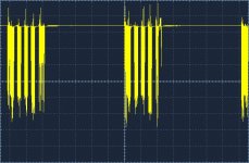
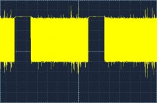
Putting the scope on the Cathode, the voltage between black and white screens is confusing me. Black screen appears to have a constant high voltage between the blanking periods,
Black screen
Black screen.jpg
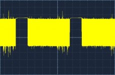
and the white has a signal that falls towards the 0V (E)
White screen
White screen dim.jpg

However, looking at the circuit, the video signals drive a push pull amp with the contrast setting the gain from a 5V signal. Interestingly, there is a 5V adjustment on the board.

Tweaked up the 5V and the screens contrast has increased :)

Looking at the signal at the cathode, the voltage has risen about 10V.

White screen dim.jpg White screen.jpg

With all the messing about with the yoke, the linearity is a bit off and might be over driving things a bit, but hey it works.
 
Back
Top