• Please review our updated Terms and Rules here

Wavy Vectrex Grid

wootwootman

Member
Joined
Dec 10, 2024
Messages
15
I recently inherited three Vectrex consoles in various states of (dis)repair from a family friend, and I'm dead-set on trying to get at least one of them up and running. The one shown in the attached pic is probably the one closest to running properly so I wanted to try and tackle it first.

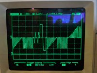
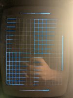
After opening the case on this particular unit, I was surprised at the lack of dust, which led me to believe that the unit had been re-capped recently. Looking at the integrator caps seemed to confirm this, as they appear to be the red rectangular caps as opposed to the older silver cylinders. Upon powering on with the test cart installed, the grid appears wavy as seen in the pic, and does not appear to move around. Also, I haven't been around a Vectrex in many years, but I believe it may be buzzing a little louder than usual.

If anyone has some tips or is willing to help out, let me know. I have a multimeter, oscilloscope, and entry-level soldering station so I should be able to at least take measurements and swap/repair components as needed.

vectrex_warp.jpgvectrex_intensity_screen.jpg

Edit: I have found a previous Vectrex related thread where Dave provides extraordinary assistance. I'll go ahead and get the service manual to start working through the troubleshooting guide.

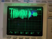
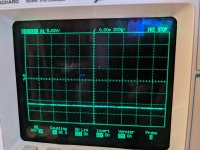
Would connecting my scope to the two axes in XY mode possibly show a rough estimate of the CRT display? Maybe I can use that to track the signal through the analog side, though I suspect it may be a larger issue, since it seems both axes are affected
 
Last edited:
Working my way through the troubleshooting guide, the initial power rail checks seem fine as does the fuse. The X- and Y-axis signals do seem a bit noisy on the power board. I checked these signals on both ends of the cable, and they're attached below.

However, I did seem to stumble upon something interesting. I started to try my XY mode idea, and with a scope probe GND clip on the braided wire, as soon as I touched the probe tip to one of the inputs (Pin7/8) on IC401, the buzzing became noticeably quieter and the grid significantly improved. When I then included the second probe on the remaining IC401 input, the buzzing went down even further and the grid became almost perfect. Does this indicate that the probe capacitance/loading may be making up for some low/missing capacitance? If so, would adding a small amount of capacitance to these signals fix things, or would that merely be a "patch"?

I suppose I can also swap out IC401 from one of the other units and hope it's functioning, but that sounds like kind of a pain.
 

Attachments

  • LogicBoard_X-Axis.jpg
    LogicBoard_X-Axis.jpg
    2.9 MB · Views: 4
  • LogicBoard_Y-Axis.jpg
    LogicBoard_Y-Axis.jpg
    2.5 MB · Views: 3
  • PowerBoard_X-Axis.jpg.jpg
    PowerBoard_X-Axis.jpg.jpg
    2.4 MB · Views: 4
  • PowerBoard_Y-Axis.jpg
    PowerBoard_Y-Axis.jpg
    2.8 MB · Views: 4
Welcome to VCFED.

Dave here!

You will be under moderation until you get ten posts under your belt, but good work so far.

I will have a look at your oscilloscope traces a little later. Just on my way to work.

Adding a small amount of capacitance is a "bodge", even if it does appear to fix things I am afraid!

Dave
 
The "logic board X/Y" signals are good.

The "power board X/Y" signals are noisy - as you have surmised.

1. Exactly which Vectrex machine have you got?

2. Exactly where did you measure the X/Y signals on the power board? You say on "both ends of the inter-board cable" [my words of what I think you were saying]. If so, have you checked the solder connections and 'cleanliness' of the contacts (on both the plug and socket) of the cable and connectors at both ends. Over time, you can get 'ring cracking' around the solder joints.

3. I am just wondering where you had the oscilloscope ground clips when you took both sets of measurements (logic board and power board). I am just wondering whether the problem is actually related to the power board - or whether the 'noise' is actually on the ground lead (0V) of the power supply from the power board to the logic board? This is unlikely, but I have been caught out before with strange things! If

4. When you say you checked the power rails, does this include the +/- 9V rails (these feed IC401).

5. IC401 has been known to fail with peculiar results on the screen - but they have tended to 'vary' on the screen with temperature. Of course, there is probably a small subset of these that fail in a different way! If you can see some 'noise' in the power board end of X/Y cable, I would resist the urge to replace IC401 at this point in time though until we have checked where this noise is coming from.

Another thought is a dirty solder side of the PCB (e.g. flux). Over time, the flux can become conductive. Flux should always be cleaned off after soldering!

The 're-cap' may indicate that this board has been repaired [sic]. The re-cap would (in all probability) have been done first - as a 'cure all'; but probably didn't work. So, automatically, we are looking for a more difficult fault...

Dave
 
1. It's one of the "regular" 3GE models. Though I've now surmised that there was a de-buzz circuit added, but I do not believe this has much to do with the issue (but I could be very mistaken).

2. These captures were taken with the scope probe tip (no witch's hat) pressed firmly to the solder pads on what would be considered the bottom side of the power board. I have cleaned up the connector on the logic board end, however I have not done the power board end yet. This is the first thing on my to-do list

3. The ground clips were on the braided grounding cable between both boards, closer to the logic board end. I suppose it would be easy enough to add a few more grounding point with wires + alligator clips.

4. Yes, I checked those with a multimeter and they seemed fine. I understand the troubleshooting guide has a ripple check as one of the later steps, so I'll skip straight to that.

5. Agreed. I'd consider an IC401 replacement more of a last resort. If it weren't for the heatsink, I'd try some cold spray on it and look for changes.


Current to-do list:
  • Clean up XY connector on power board (deoxit and light sanding)
  • Add more GND points between logic and power boards
  • Check ripple on both power rails to IC401. The troubleshooting guide has the ripple at the input of T501 at <50mV. These two rails also feed T401 which is the transformer for IC401. I suppose I can also check capacitance, as a quick glance shows the +9V rail should have a bit over twice the capacitance of -9V (~23mF vs ~11mF)
  • See if the noise on the X-axis power board signal is less noisy when I touch the probe tip to the X-axis input on IC401
  • Add a small (pF-nF range) amount of capacitance between IC401 pins 7/8 and ground to see if my backup plan would work
Thanks for the reply Dave!
 
>>> Thanks for the reply Dave!

No problem.

If you have an oscilloscope, it is always better to check the power rails with the oscilloscope rather than a multimeter.

Look for the DC level. Any ripple at 50, 60, 100 or 120 Hz (smoothing) and then increase the timebase to look for higher-frequency noise.

Dave
 
Neither cleaning the connector surfaces not adding more grounding points had an effect.

I had some 120pF ceramic caps on hand and adding one to either Pin 7 or 8 of IC401 appears to have a similar impact as the scope probe, so it's good to know there's at least one working option.

The real discovery was on Pin 1 of IC401. When checking the ripple on the +9V and -9V rails going into IC401, I saw a lot of noise on Pin 1. The scope channel was AC coupled so I went back in DC coupling. The attached pics are of IC401 Pin1/3.

At this point I'm waiting to borrow an LCR meter to measure the capacitance at those power pins, and I'm also considering adding a few hundred uF capacitor to Pin 1 to see if that smooths out the noise.
 

Attachments

  • IC401_Pin1.jpg
    IC401_Pin1.jpg
    2.8 MB · Views: 4
  • IC401_Pin3.jpg
    IC401_Pin3.jpg
    2.5 MB · Views: 4
Interesting.

+9V feeds a few more places other than IC401.

It also feeds the CRT High Voltage generator (as does -9V) and it feeds the audio amplifier. You did remark that the machine was humming a bit more than you thought it should.

I am leaning towards an IC401 fault to be honest... Than can 'suck' a fair current under fault conditions. However, a dicky capacitor (less likely) or faulty solder joint could also cause a similar issue (possibly). Just thinking of the possibilities...

Just had another thought whilst eating my evening meal.

The supply for IC401 is routed via T401.

Measure the noise on the 'main' +9V supply directly from the bridge rectifier (i.e. on the IN side of T401).

Look at T401 for signs of distress, and at the solder joints associated with T401 along with the integrity of the PCB tracking between T401 and IC401.

Dave
 
Last edited:
To-do list for this evening:
  • Visually inspect T401, its solder joints, and all associated traces
  • Check noise on all four T401 pins referenced to ground
  • Verify C401 and C404 are present and making contact (C401 may be difficult due to location under heatsink)
  • Check if the trace for IC401 Pin 1 runs on the top or bottom of the Power Board
    • If it's accessible on the bottom side, cut the trace and see if the noise goes away on T401 +9V OUT side. Repair trace with solder blob
    • If it's on top side, add capacitance to IC401 Pin 1 starting with 0.1uF (value of C401) and moving on to a few hundred uF (approaching C404)
I'll go ahead and start looking for a replacement IC401. Even if it's not at fault here, I still have two other Vectrex units I need to work on.
 
Sounds like a plan to me.

I would 'repair' the cut track with a piece of stout wire and solder rather than just solder though.

Is there any way of breaking the +9V supply to IC401 without cutting a track though. Always the first choice...

 Dave
 
Unfortunately I doubt IC401 is socketed, and I don't think i can just unsolder Pin 1 and bend it outwards 90 degrees :cautious:
 
Also, if you are going to remove IC401, make sure to have some new heatsink compound to hand.

The old heatsink compound will have degraded, so will need to be cleaned off and new applied to aid the thermal transfer from IC401 to the heatsink to the atmosphere...

Dave
 
Ah, thanks for the reminder. Fortunately I have a few tubes of CPU thermal paste which should do the trick. The new IC401 may arrive this weekend, so it's possible this unit can be wrapped up in the next few days 🤞
 
I had a 47uF electrolytic cap in my parts box that I ended up attaching to IC 401 Pin 1 on the bottom side of the power board, and it seemed to clear things up right away. At this point I'm assuming one of the bypass caps under the heatsink was either not replaced or was improperly soldered when the recap was done. I'll run it through it's paces for a few days and set it aside to start on the next one. Stay tuned
 
I would check any external capacitors on the +9V rail first. They will be much easier to check!

Did that fix the improper screen visuals?

Dave
 
Yup, aside from a very slight offset between the left and right sides, it's basically fine. I'm sure some more fiddling can clear that up but at this point I'm satisfied with its' current condition.

Edit: Do you happen to know the screw sizes for the case? There's only about 5 screws between the three units
 

Attachments

  • Vectrex1_grid.jpg
    Vectrex1_grid.jpg
    483.3 KB · Views: 4
Last edited:
Yes, that looks fine. So it is likely a capacitor (or bad solder joint on a capacitor) rather than IC401.

Dave
 
I finally got around to looking at the second unit. Upon powering it on, there was no sound or "boot screen" which was a bit disheartening, however I did get a white dot in the middle so I knew the HV portion was likely functioning. I recalled some of the other threads I had come across online, so I went ahead and turned the brightness down far enough to just barely see the dot as to avoid burn-in.

After probing around a bit, I noticed that while there was activity on IC203 Pins9/10 (inputs to an OR gate), there was only a static ~4V on Pin 8 (OR gate output). This IC turned out to be a 74LS32 Quad 2-Input OR Gate which had at least one of its' gates fail. There's also the possibility that the gate associated with Pin 8 is fine, and the failure may be with an IC that is connected to this pin (IC204 Pin 8 /CS & IC205 Pin 8 /CS).

IC203 is directly soldered to the PCB but IC204 & 205 are socketed so I should be able to just remove those and see if there is movement on IC 203 Pin 8.

This unit has not be re-capped, as it was quite dusty and still has the original silver integrator caps (which will be replaced soon). I noticed at least one component (C307) with a leg just floating in the air, so I'm aware that even getting a picture on the display is still only partway to fixing this particular unit.
 
After removing both IC204 and 205, I was able to see activity on IC203 Pin 8. After re-seating the original IC205, I still saw activity on IC203 Pin8, as well as after putting the original IC204 back. I'm left to wonder if the RAM ICs just needed to be re-seated? I hit the sockets with some cleaner while they were unpopulated, so maybe that helped.

I moved on to poking around IC207 and noticed there was some oddly shaped signals on Pins2-9 (VIA PA0-7). Ultimately, I just swapped out IC207 (MOS 6522A) with the known good one from the functioning Vectrex, and upon power on, I was able to hear the boot sounds along with the Mine Storm gameplay audio. Pressing the fire button on the controller also elicited the correct sound, so I knew the game itself was running on the system, there just wasn't any visuals. In fact, the white dot was a little dimmer, which made me wonder if the Z-axis data had also been effected by the IC207 replacement. Also, the dot was no longer in the enter and had moved a bit towards the upper right corner.

Since the audio and controller seemed to work fine, I skipped most of my checks on IC208. This left the IC30x chips as the most likely source of the issue. I went ahead and pre-emptively swapped out IC301 and 302, but there was no change. I moved over to the IC305 quad switch, and while the control pins did show activity from +5V to -5V, the inputs did not show any meaningful activity. Checking the outputs of IC302 also led nowhere.

I went back to IC301 and started on the basic voltage checks, but quickly realized the rails as measured on the IC pins, not the socket pins, were wildly out of their expected ranges. The most concerning value was -8.1V on Pin 13 (which should be +5V). After removing the IC and checking the voltages on only the socket, they seemed fine. I re-seated IC301 and did some continuity checks, which resulted in me discovering that some of the IC pins were not making proper contact with the socket itself. Applying some slight physical pressure to the pins confirmed my suspicion, so I will be replacing that socket sometime in the next few days. At this point I'm wondering if I can just wedge the thin legs of a ceramic capacitor alongside each IC pin to apply constant pressure on the affected pins and see if that makes a (temporary) difference.

TL;DR after some IC swaps with known good ones, the issue may now be a bad socket under IC301
 
Back
Top