• Please review our updated Terms and Rules here

What did I do to my PDP-8 today.

Nice. I didn't think about doing the disassembly although it would have been easy as I have a subroutine in my emulator that does it for trace dumps.
Probably too late to help much now, but an early step I've used for this kind of work is to go to the end of the PDF where the symbol table was dumped. I start by typing that into a ".syms" file, one symbol-value pair per line. The bin2pal disassembler will read that when disassembling the original binary, which dramatically reduces the work to converge the disassembly with the source code in the PDF.
 
I was thinking, wouldn't it be nice if I could just ask Chatgpt to convert the PDF documentation into ASCII text. I've tried using OCR but so far it has been more work fixing the output than keying it by hand. But even if OCR or Chatgpt were perfect I would still have to go through the code to understand what they were trying to do.
 
I worked with Vince yesterday. We didn't really have a plan of what to work on. He had built up a new set of upgraded boards that make up his memory expansion for the 8/I and PDP-12 and it had done nothing when plugged into his 12 so I said lets get that working. The first set ran well most of the time but sometimes had issues when powering up. This set has fixes for the power up issue. The memory expansion slots are not powered since they are supposed to be for cables running to the MM8I expansion so there is a 6th board that plugs into a nearby unused slot with 5V. Turned on the machine and found there was no 5V at the cards. Moved the power card to a different slot and now we have a working memory expansion. Loaded up a memory checkerboard and found that it didn't run properly. Eventually we found the issue was that this particular test is for the 8/e and made extensive use of the BSW instruction which does not exist on any machine pre 8/e. I located the test intended for the 8/i and Straight and we ran that without issues for more than an hour.l I also located a checkerboard intended for the PDP-12. This test is written in LINC mode and we ran that one as well for quite a while.

I also got a chance to boot the pre-release of version 1.2 of Console Serial Disk on the 12 and found no issues. I didn't expect any but it is nice to test.

We also talked about the cable replacements for the Posi and Negi bus that Warren had worked on and Vince had actually built. They are an interesting arrangement made with a ribbon cable that is twisted pairs but has a flat section every 18 inches where it can have a connector. That makes these cable some multiple of 18 inches in length. They should probably be tested for signal reflections which is what we talked about doing but didn't get around to. I have seen SCSI cables built using this kind of ribbon cable and they work at much higher frequencies than is needed for these kinds of signals. I neglected to take any photos but maybe Vince will post a follow up with some.

I am still working on keying the source for maindec-8e-d0ab from the pdf and feel like the home stretch is in sight. I have found maybe half a dozen errors where it does not test what it says it tests in the comments or tests using instructions that have not been previously tested. One example I can give here is a code segment that looks like this.
Code:
SNL
SZL
HLT
The first skip will activate if the link is non zero and the processor will halt because the link is supposed to be zero. The second skip will activate if the link is zero and skip the halt. The second skip is supposed to be SZA because the result of the test case that came before this is supposed to be AC=0000, L=0. Clearly this was a 50 year old typo that nobody caught. Did it ever cause the test to fail to find an issue? Probably not since most things are tested several ways and the kind of error that would have been triggered by this particular test case would probably also been caught somewhere else. This was a test of one of the complicated OPERATE combos. Something like CLA CMA CLL IAC RAL which only works on the 8/e. I will probably get this finished up in the next few days.
 
Been supporting the local museums. The VCF straight 8 was acting up again. Found it didn't want to jump. Poking around the load MA to PC 5-11 signal wasn't getting to the PC card. R603 pulse amp in PD20 was the cause. Seemed to be bad transistor this time. Swapped in a spare I brought. Will fix card later.
I am pretty sure I had this same problem. I probably still need to fix that board as well.
I was reminded near the end that they had crashes if backplanes moved. Verified it occurs but too late to mess with so it will wait till another time.
I have not had this issue. I look forward to hearing more about the solution.
Other remaining problem is front panel flaky from switch bounce. Have cleaned best can with spray cleaner a couple times. Fixes for a while but comes back. Mine same though not a bad. Since the switches are custom for the rocker handles don't know where to get replacement. Will look into making inline debouncer for the cable.
This seems to be a common problem. I can't remember, are those double throw switches? If they are then I think maybe replacing the front panel with one that has a flipflop for each switch would be a permafix for this issue. Also fix the fragile bulb wires issue and the delaminating foils issue. For those that don't know, the bulbs on the Straight 8 have these hair thin wires that can barely support the weight of the bulb which makes reassembly without breaking wires somewhat difficult. Also the PCB material seems especially heat sensitive and there are lots of lifting foils on my front panel from before I got the machine.

I'll make BASIC tape also. Anybody have idea of non game programs that general public would understand and can be demoed in reasonable time? Right now its 8k 8/I with high speed paper tape and teletype. DECtapes not yet restored.
This is a more difficult request than I had thought it would be. I will keep thinking about it. I hope someone thinks of something because games tend to be the demos everyone uses.

Thanks for the update!
 
This is a more difficult request than I had thought it would be. I will keep thinking about it. I hope someone thinks of something because games tend to be the demos everyone uses.
There were some less games such as bounce which simulated bounce of a ball, 3d plot to plot a function.

Went back last weekend. I never found the adjustment procedure for the tape reader so was doing it like I remembered for my 8/E. 8/I doesn't use the feed hole for strobing the data. It uses it for end of tape detection so during normal operation you shouldn't see feed holes. It uses stepper phase to strobe the data.

Tried to load over the console port from my laptop and tape wouldn't load. Tried echo toggle in program and found most of the time it detected the character being sent but received it as all 0's. Switched to teletype and it had similar faults but when the character was received it wasn't right. Switched to local and found the teletype had a stuck bit. Control did clear the stuck bit.

The 8/I problem was IOP4 pulse was not generated most of the time. Traced it to bad M310 in F16. The output pulse was misshaped. Tried the reader but it didn't want to work. Decided to check how my 8/I reader worked when I got back home so moved on to the LINC power supply for the rest of the day. Figured out on my machine that 8/I reader adjustment is different that 8/E. Adjusted System Source reader and still didn't behave. Since test equipment was with LINC supply decided to continue on with LINC. Ran out of time so didn't get to troubleshoot reader further.

Traced the inability to adjust the -18V supply to a bad transistor in the differential pair use to compare the voltage to the reference. With it replaced worked fine. -3V problem was their was too much leakage so the final transistor was turning on when the regulator had it off. I swapped the transistor I though was causing it without improving it. Added a resistor to bleed off the leakage into the base and that fixed the regulator. Did some reading up later on germanium transistor leakage and likely misidentified the transistor causing the problem. Next time we have supply out we will check the other transistor and replace if it is the cause.

Load tested all output and check ripple under load to verify reasonable and symmetric at 120 Hz showing all rectifiers were good. One was a little asymmetric but decided wasn't that bad so didn't try to replace it. When we finished it was too late to install. They put it in later and it looked good. End of January is next workshop to do further work on LINC and 8/I. The bearings in the LINCtapes were replaced previously but sealed bearings were used. The drag was too much so couldn't get the drives adjusted according to the manual. We will replace with shielded and hopefully can then adjust then run diagnostics to see what more needs fixing.
 
I finally finished up the recreation of maindec-8e-d0ab-pa which is the source code for Instruction Test 1 on the 8/e. When assembled with palbart the binary output matches exactly the 53 year old DEC generated binary. I asked Vince to check my work and he said it matched with his tools as well. I want to be clear that this is not a reverse assembly of the binary, I keyed in the program from the listing found in maindec-8e-d0ab-d.pdf that can be found in several archives. The goal was to make it as close as the original lost source. I kept all the typos and hopefully didn't add too many of my own. (I really hope someone has the original paper tapes and they surface!)

The original consisted of four paper tapes fed into some version of PAL. I commented out the PAUSE pseudo ops and made it all one file. It would be trivial to break this into four pieces at the PAUSE pseudo ops. It would have been a difficult guessing game to try to insert the editor page breaks from the PAL10 listing in the documentation so I didn't try to do that. I guess if you want to break it up into four pieces and then add in the editor page breaks, have at it!

I documented all the bugs and typos I found and included that with my notes after the $ that ends a PAL8 program. I felt this was better than having a separate document that could easily get separated from the source.

Now the question is what should I do with it? I hope Vince will put it on his website but optimally I would like to see it show up on Bitsavers. What are peoples thoughts on this?
 
the question is what should I do with it? I hope Vince will put it on his website but optimally I would like to see it show up on Bitsavers. What are peoples thoughts on this?
Sounds like a major project to re-create a valid PAL source for that diagnostic program. Yes, I'd suggest it might be worthwhile to have it hosted on Bitsavers as well as SoMuchStuff.
 
Now the question is what should I do with it? I hope Vince will put it on his website but optimally I would like to see it show up on Bitsavers.
I put your early version online already, and would be happy to replace it with your latest. Are you still planning to work on 8e-d0aa as well?
 
I put your early version online already, and would be happy to replace it with your latest. Are you still planning to work on 8e-d0aa as well?
Ok. I will send it to you tomorrow. I want to look at my notes one more time.

I am going to do 8e-d0aa. I am reasonably certain that they are not that different so it should not take too long. The reason for doing so is I am curious about what got changed. I am also going to back and look at the Straight 8 version and see if these are actually descended from it or if it got re-written at some point.
 
I generated maindec-8e-d0aa-pa and sent it to Vince. Surprised me that it took less than 15 minutes to get the binaries to match.

The differences between d0aa and d0ab are they more than doubled the pass count between ringing the bell and added TAD TEST 37 through TAD TEST 60.

It is clear that d0ab is a direct modification of d0aa. Still haven't looked at the Straight 8 version to see if it is an ancestor.
 
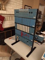
.. nice. It took a moment to recognise the DEC logo in the lower-right corner. Would that have been the inspiration for the DEC Logic Lab or a custom test setup?
 
.. nice. It took a moment to recognise the DEC logo in the lower-right corner. Would that have been the inspiration for the DEC Logic Lab or a custom test setup?
It's a Logic Lab, of the vintage shown on page 207 of the 1967 Logic Handbook. I also have the Analog panel, as shown on the back cover of the 1967 Logic Handbook. It's similar to the K series Logic Lab in the 1973-1974 Logic Handbook, though older (and negative logic). The M series Logic Lab pictured therein looks rather different, though.
 
Vince, are you going to build a modular synth? :love:
I'm not sure how to do that. There's only the one 4 bit DAC and a comparator, and I can't even figure out which module goes in there to make that work. Cool meters, though, if I can figure out how to drive them.

I figured something with the switches and lights. Maybe a cool "idle pattern" or kill-the-bit, that sort of thing. (The adjustable frequency clock to set the difficulty.) The telephone dial is also too cool not to use, though. So far, I've found suitable replacement switches, lights, and meters. I don't have the W501(x3), so I've had PCBs made. I don't have the R121(x4), R122, R302(x2), or R602 modules on hand either, so I'll need to find or make those. (Otherwise the cool plastic inserts with the logic diagram pin-outs won't be right.)
 
Back
Top