• Please review our updated Terms and Rules here

What is the most complicated bootstrap scheme?

Plasmo

Experienced Member
Joined
Aug 29, 2017
Messages
217
Location
New Mexico, USA
I recently designed a minimalistic, but CP/M-ready Z80 SBC. The motivation is to build a high performance CP/M computer kit for $20. To save cost, I use the CF disk as boot EPROM. To initialize a blank CF disk, I have a simple serial port that loads succession of software that finally wrote the necessary bootstrap code into CF and then the CP/M BIOS/CCP/BDOS and system files into CF disk. the process is documented here. https://www.retrobrewcomputers.org/doku.php?id=builderpages:plasmo:zrcc:zrcc1:cf_installation

It is complicated, but can be automated with a script file. I'm rather pleased with this Rube Goldberg bootstrap scheme. If there is a competition for most complicated bootstrapping, I would enter it. My question is what was the most complicated bootstrap procedure you guys can think of?
Bill
 
Xerox sold the 16/8, a CP/M computer which can boot and run MS-DOS v1.25.

The 16/8 is essentially an 820-II, a Z80 computer with an 8086 on an additional coprocessor card.

When booting MS-DOS on that system,

1. Boot CP/M
2. Load interprocessor communications code onto the 8086
3. Load interprocessor code onto the Z80
4. Transfer control to the 8086
5. Boot a customized version of MS-DOS

All of this is automated and hidden from the user, thank goodness.
 
There were several systems that did that, usually using the 8 bit processor for I/O. The Radio Shack 16, for example, always boots the Z80 first, then loads CP/M-68K or Xenix into the 68000. Durango used a 186 to provide the I/O for a 286. This is an idea that's been around for a very very long time.

IIRC, many supercomputers implemented only a wide high-speed channel for I/O, leaving the actual interfacing to peripherals to a lesser (e.g. IBM S/370) third-party machine.
 
I acquired a disk controller that I knew nothing about to use in a IMSAI that I picked up cheap. I wanted to get CP/M 2.0 working on it. The disk controller used a ROM based state machine to control reading and writing to the disk. It was a DMA device, unlike most of that days S-100 controllers that required a boot ROM on the S-100 bus to run the disk controller.
The controller was vary low level. I decoded the controller and determined what information the S-100 system needed to read and write data to the floppy sectors, as well as how to get it to format the disk tracks. I determined that it would, on reset DMA one sector of the first track to the address 0.
I needed to get the first level boot strap onto the first tract. I did this by writing the code externally on a old 486 laptop. I'd then toggle a simple serial in to memory that I used to read serial data from the laptop to the S-100 memory and then I'd use my knowledge of the disk controller to write the first level boot strap to the first sector of the first tract. Luckily the serial on the early S-100 boards needed little initialization software. I'd then use the same serial to transfer the BIOS code, that I wrote for the CP/M that also knew about the serial and the disk controller. Slowly I transferred images of various programs to the S-100 over the serial link and then dump them onto the disk using CP/M utilities.
The neat thing about this controller is it needed no memory on the S-100 to run. 64K of total with no holes RAM!
I'd never have been able to figure out the controller if it were not for someone having a copy of the schematic. I was also lucky that my controller had the extra ROM used to format the disk.
I've done a few other projects, making a boot strap for the HeathKit H89 and later the H8. I've also worked with a fellow in Germany to get CP/M-8000 working on an Olivetti M20 ( not to be confused with the M24 ). For that project I wrote some code to write directly to a AT controller used to transfer floppy images to for the M20. This required a controller capable of formatting and writing single density on the first track and double density on the remainder of tracks. Not all of these controllers could do that. I then used an early X300 type disk controller from a 5Meg Tandy box to interface with the M20 and used a Seagate 251 that needed a patch to the M20 floppy disk image to change from fixed step rate to auto, like the original Olivetti disk.
No I'm playing with getting some old software working on a 4004 processor.
Dwight
 
I enjoyed reading about bootstrapping schemes. It is an important but obscure corner of electronic. Most of the time it is done only once and frequently in the factory, the associated connector and electronics are the bare minimal, yet it is the first thing you work on when an electronic comes on line or when it quit working. Lots of interesting ideas in that corner of the world.
Bill
 
Hey, at least you have your 64 bytes of ROM to kick things off. If you had an Altair or other early "front panel" machine with no boot ROM you'd have to key in your serial loader via the front panel. Here's a page linking to a bunch of videos showing how to make an Altair do various things, the one about loading 4k BASIC includes a link to the 20 byte serial loader you had to key in to get it off the paper tape. And there's another video that demonstrates how to get a floppy disk booted without a boot ROM via the convoluted process of keying in a serial loader to read in a paper tape that has the FDC boot program on it.

The Apple II disk controller uses a 256 byte boot prom, but a large portion of that is dedicated to routines for driving the actual mechanical action of the disk drive (there's no disk controller chip, per se) and the routines/translation table for its 6-in-8 GCR encoding. Kind of impressive code density there, I guess.
 
The 64 bytes of ROM code synthesized out of logic fabric of a modest CPLD was unexpected. I didn't know I can have so much ROM, and still have logic left over to do meaningful functions. It was an improvement over my previous minimalistic design that has no ROM but implement a serial port and DMA in CPLD to load battery-backed RAM the first time and then boot out of RAM in subsequent power cycle.
Bill
 
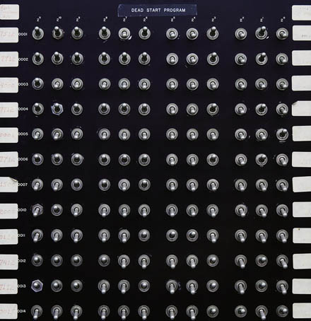
You mean, like a CDC 6600?

Control-Data-Corporation-CDC-6600-015FINAL_LARGE_final.jpg


The somewhat later Cyber 800s used a 16x16 array of switches.

Later large machines were even more complicated, so small drums or disks were included in the control processor. On the STAR, reloading the MCU drum involved attaching a CE maintenance box and loading in from paper tape...

I should mention that in the 6600 example above, that the switch program read a single block from a tape drive into PP 0. It was then the job of the loaded program to start the other peripheral processors, transfer code to one of them to initiate disk access and begin reading the remainder of the tape and selectively copying it to disk. The CPU was started only after all of this had occurred. No ROM back then--you had 144 switches.

In the example above. certain deadstart configuration parameters had to be specified as well. Unused bit fields in the instructions were used for this.
 
Last edited:
I once came across one of the later Crays, a Y-MP EL and that used another machine with a JTAG interface to load the boot image onto it and get it started.
 
>>used another machine with a JTAG interface
and the DEC alpha processors booted by loading a serial ROM into their icache.. and then you could use the interface pins as GPIO and bit-bang an RS232 link..
 
>>used another machine with a JTAG interface
and the DEC alpha processors booted by loading a serial ROM into their icache.. and then you could use the interface pins as GPIO and bit-bang an RS232 link..

Interesting. In Tiny68K I use serial EPROM and a state machine in CPLD to fill DRAM memory then release 68000 to run. Don't have to deal with 16-bit EPROM this way.
Bill
 
Booting the Altair 8800 disk without the Altair DBL boot PROM was quite the process. The disk boot loader was available on paper tape for this purpose. The entire process went like this:

1) Enter a bootstrap loader on the front panel to allow the Altair to load from paper tape.
2) The bootstrap loader reads in the checksum loader from the start of the tape and hands off control to the checksum loader.
3) The checksum loader reads the rest of the paper tape which has the code for the disk boot loader. Control is given to the disk boot loader.
4) The disk boot loader reads track 0, sector 0, from drive 0 into memory and gives control to the loader just read in from disk.
5) The loader read from disk then completes the boot process by reading in BASIC, CP/M, etc., from disk.

Here's a video of the process https://www.youtube.com/watch?v=FKNayPnZT54

Mike
 
Back
Top