Upcoming Events:
| VCF West | Aug 01 - 02 2025, | CHM, Mountain View, CA |
| VCF Midwest | Sep 13 - 14 2025, | Schaumburg, IL |
| VCF Montreal | Jan 24 - 25, 2026, | RMC Saint Jean, Montreal, Canada |
| VCF SoCal | Feb 14 - 15, 2026, | Hotel Fera, Orange CA |
| VCF Southwest | May 29 - 31, 2026, | Westin Dallas Fort Worth Airport |
| VCF Southeast | June, 2026 | Atlanta, GA |
-
Please review our updated Terms and Rules here
You are using an out of date browser. It may not display this or other websites correctly.
You should upgrade or use an alternative browser.
You should upgrade or use an alternative browser.
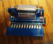
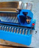
Whats the purpose of this jumper on this ieee-488 adapter?
- Thread starter VERAULT
- Start date
jlang
Veteran Member
The system controller is the only device allowed to drive IFC (interface clear)
I expect the jumper is set to allow the PET to be system controller.
I expect the jumper is set to allow the PET to be system controller.
VERAULT
Veteran Member
- Joined
- Jan 30, 2012
- Messages
- 9,999
So it will be fine with no jumper than?The system controller is the only device allowed to drive IFC (interface clear)
I expect the jumper is set to allow the PET to be system controller.
VERAULT
Veteran Member
- Joined
- Jan 30, 2012
- Messages
- 9,999
So i booted up my other PET. And It seems the issue is my IEEE-488 Bus on one of my pets is no longer working. Swapping the socketed ic's resulted in no change. After doing some reading I think the issue is the MC3446N Bus Tranceivers. I put in an order for some.
Eudimorphodon
Veteran Member
So it will be fine with no jumper than?
If you flip that thing over can you trace what the jumper disconnects? It's possible you have to have it set by default and no jumper disconnects it? Of course, off the top of my head I have no idea if the PET drives require it connected or not.
stepleton
Veteran Member
(wild guess) As it's a three-pin jumperheader, there's a chance that (for example) pin 1 is GND, pin 3 is some "source" signal pin, and pin 2 is IFC. Bridging pins 1-2 pulls IFC to ground, bridging pins 2-3 makes it do whatever the source signal pin is doing, and running with no jumper lets one of the computers drive IFC.
It could be a different configuration, but my point is that "no jumper" could select one of up to three options that thisjumperheader makes available. But the actual traces will tell the real story.
(ETA: got too enthusiastic about the word "jumper", probably because it's a chilly April evening!)
It could be a different configuration, but my point is that "no jumper" could select one of up to three options that this
(ETA: got too enthusiastic about the word "jumper", probably because it's a chilly April evening!)
Last edited:
Hugo Holden
Veteran Member
Where did you put in the order ?So i booted up my other PET. And It seems the issue is my IEEE-488 Bus on one of my pets is no longer working. Swapping the socketed ic's resulted in no change. After doing some reading I think the issue is the MC3446N Bus Tranceivers. I put in an order for some.
Unfortunately there are a few fakes of these now. But I know the source for genuine original vintage parts, if you get stuck.
daver2
10k Member
There is a test program for the IEEE-488 port on the PET written in BASIC. Type it in and RUN to test the port (without anything connected to the bus of course).
This code was in a book, and it is available online as a PDF.
Unfortunately, I am on a business trip this week, otherwise I would reach onto my bookshelf and post the details for you.
Perhaps someone else could oblige?
Dave
This code was in a book, and it is available online as a PDF.
Unfortunately, I am on a business trip this week, otherwise I would reach onto my bookshelf and post the details for you.
Perhaps someone else could oblige?
Dave
VERAULT
Veteran Member
- Joined
- Jan 30, 2012
- Messages
- 9,999
You know I was trying to find an email to tell me where.. But I just couldn't find one. I bought it a few years back and I am not sure where.Where did you put in the order ?
Unfortunately there are a few fakes of these now. But I know the source for genuine original vintage parts, if you get stuck.
ScottishColin
Experienced Member
The program is on P 199 of this book:

Colin.

PET and the IEEE 488 Bus (GPIB) : Fisher, E. R. (Eugene Ralph), 1940- : Free Download, Borrow, and Streaming : Internet Archive
PET and the IEEE488 Bus (1980)(McGraw-Hill)
archive.org
Colin.
Gary C
Veteran Member
I imagine the pin connected to nowhere is so you can store the jumper from red to ? when not in use.
VERAULT
Veteran Member
- Joined
- Jan 30, 2012
- Messages
- 9,999
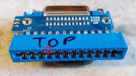
I was thinking the same thing as a possibility. So what does bridging the IFC pin to pin 9 of the card edge do exactly?I imagine the pin connected to nowhere is so you can store the jumper from red to ? when not in use.
Eudimorphodon
Veteran Member
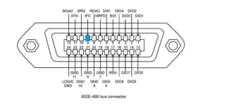
Pin 9 is IFC, like it says on the tin. So no jumper there means IFC is not connected.
Looking at the schematics for the Commodore 4040 and 8050 disk drives it doesn't look like they have anything attached to that line, so I would presume for running a disk drive it wouldn't matter if you had that jumpered or not, but there's probably no harm in trying it either way.
Looking at the schematics for the Commodore 4040 and 8050 disk drives it doesn't look like they have anything attached to that line, so I would presume for running a disk drive it wouldn't matter if you had that jumpered or not, but there's probably no harm in trying it either way.
Gary C
Veteran Member
It inverts reset so when the PET gets a reset, the interface clear line is pulled and all devices no matter what they are doing immediately let go of the line and await further commands (if they follow the IEEE-488 spec).
dave_m
Veteran Member
Gary,It inverts reset so when the PET gets a reset, the interface clear line is pulled and all devices no matter what they are doing immediately let go of the line and await further commands (if they follow the IEEE-488 spec).
That is correct, but note that the /Reset signal is not inverted (the 7417 is a non-inverting buffer). The /IFC is also a LOW active signal.
Gary C
Veteran Member
Oh yes 
dave_m
Veteran Member
Hi Eudimorphodon,Looking at the schematics for the Commodore 4040 and 8050 disk drives it doesn't look like they have anything attached to that line, so ...
It's a bit hidden on the lower right of the sheet 1 schematic for the 4040, but /IFC is connected to the 555 timer circuit and will reset the 4040. Whenever I reset the PET, it does recycle the 4040.
So the jumper should be left in place to bridge the /IFC signal to the IEEE connector.
I only wonder why it's an option not to connect it? If one wanted to use another computer on the 488 bus as the controller and the PET as an instrument, then you could leave this connection open, but as all the canned routines in the PET BASIC are for it to act as a controller, one would need to write an assembly language program for the PET to allow it to respond properly to incoming commands.
-dave_m


