• Please review our updated Terms and Rules here

Which Debug Card to use to repair a Socket 7 Motherboard?

ayandon

Experienced Member
Joined
Aug 10, 2022
Messages
52
Location
Kolkata, India
Friends,

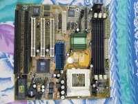
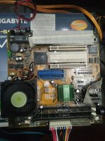
I am trying to repair my Socket 7 Motherboard - Zida Tomato T530B-S

This was my personal PC when I was a kid (not bought from scrap/others)


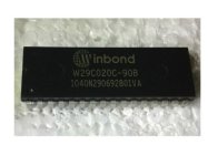
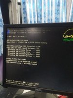
1st Stage: The BIOS IC was found to be corrupted. Can't read nor write. Replaced.

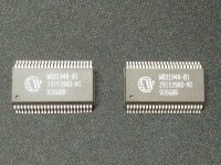
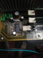
2nd Stage: There is no Clock Signal. May be the Clock IC is damaged. Replacement IC received today.


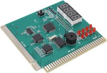
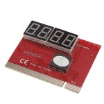
My question: Which Debug Card to use?
I have my PCI Debug Card. Do I need that ISA/PCI Debug Card?
 

Attachments

  • 1664866552669.jpg
    1664866552669.jpg
    2.8 MB · Views: 14
  • eBay-Winbond-BIOS.jpg
    eBay-Winbond-BIOS.jpg
    19.4 KB · Views: 10
  • IMG20230904183407.jpg
    IMG20230904183407.jpg
    2.2 MB · Views: 12
  • debug_card_ISA.jpg
    debug_card_ISA.jpg
    93.7 KB · Views: 8
  • debug_card_PCI.jpg
    debug_card_PCI.jpg
    108.3 KB · Views: 11
Not sure on the better debug card.

When you say there is no clock signal, are you saying that the master oscillator has stopped ? Did you verify that on the scope ?

On these boards there are a few things that can deactivate them. One is Tin whiskers between the fine pitch pins on the IC's. Although they may not have used Lead free solder, the IC pins were often Tin plated. so check under high magnification.

Also those ZIF sockets on the CPU (generally are Gold plated) They get an insulating film on their surface with age. It is not cleaned off by spray cleaning. But, if you insert some thin cardboard about 1mm thick spaced under the CPU corners and only partially close the latching arm for some contact friction, you then take the spacers out and push the CPU home and the small amount of sliding friction cleans the film off both the CPU pins and the socket connections at the same time, do it about 5 times while its wet with contact cleaner.

At least the board does not have surface mount electrolytic caps. Still it is worth inspecting if the radial caps there or the battery has leaked in the past. If so, the solder in the affected area loses its shine and gets a darkish grey color instead.
Thank you so much for these awesome tips.
 
Today, I managed to revive my old system gifted by my father.
AMD K6-II 3DNow 500 MHz with Zida T530B-S Super Socket Motherboard.
I need to replace the BIOS IC and the Clock IC.

One small issue still exists.

In this setup, 256 MB x3 RAMs are showing as 128 MB x3 RAMs!
The eBay seller already said - "It displays 256MB on motherboards above version 815, and 128MB on motherboards below version 815. It requires updating the motherboard BIOS to display 256MB"

Is there anything to do?
 

Attachments

  • IMG20240331184823.jpg
    IMG20240331184823.jpg
    921.7 KB · Views: 4
  • IMG20240331184833.jpg
    IMG20240331184833.jpg
    1.7 MB · Views: 4
  • IMG20240331184840.jpg
    IMG20240331184840.jpg
    705.9 KB · Views: 4
If you want PCI only debug cards there are great ones with an LCD screen with text of each step in the boot process.
 
Back
Top