• Please review our updated Terms and Rules here

Need help with "unresponsive" Teletek FDC-1C all in one computer-on-a-board.

Right of the {>} is the voltage when pressing reset. Do you want the RAM 16 put in?

Z-80addr.jpg
 
Last edited:
Just to clarify, the idea is to put your probe on A0, hold the reset button, read 0, release the reset button, and see if the voltage is something other than zero. 'flickering' , and repeat for some of the other address lines.
patscc
 
Well, Bruce writes me that he now has his Elenco logic probe, so perhaps we can dispense with the DMM. The LP will diagnose "pulsing" signal lines, where the DMM will just read the average voltage level.

Hope this helps.
 
1. I need to learn how to hook up the red and black leads on my new LP-560 digital probe, I assume that will change depending on the test points.

2. On an unexpected front, I hopefully will have a chance to test the terminal and keyboard on another system.

Let the next round of fun begin!

Bruce
 
Just so we're all on the same page, are you gonna try the terminal or the Compaq ?
patscc

Bad news on the old laptop. Seems that it's a historical footnote now. It, like the Viao before it, led a tough life in the field.

B.
 
How so ? If you don't mind, start another thread in the "modern" section. Describe the symptoms. They're pretty tough. There's hope yet.
Is it one of the early purple Vaio's ?
patscc
 
I've started to read through the documenation on the FDC-1C. Things to check:
  1. The FDC-1C is connected as DTE via J1 on the card. That means that you should have, DB25 pins jumpered on both the terminal and the FDC-1C side as 4-5 and 6-20 on each connector. Pin 7 should be straight across to Pin 7 on the other end of the cable and Pins 2 and 3 should be swapped from end-to-end.
  2. Your 6116 SRAM chip should be in the U37 socket and the EPROM in the U34 socket.
  3. You should press <Return> slowly several times on the terminal (set to N-8-1) until you get a logon prompt
  4. Check to see that you have the "M1" memory map configured per the manual.

HI Chuck,

That jumpering seems to conflict with the supplement, but I'll go back over all of that and try to reconcile them.

EPROM & 6116 in proper places.

Never have seen a logon prompt of any kind yet. Still hoping to see it.

M1 heh? Now you've done it! -Back to "What a dog hears"... It is going to require some time for me to understand how to check that. I'm going to need my Rhunestone. Give me a couple of days, I am going to be short on time with other demands for a bit.

I am not being flippant, I appreciate all of you'se, (that's a ChiTown-ism), putting in the time it has taken to try to help me with this hopefully worthy project. I want to see it through.

Bruce
 
Insomnia; thanks for the RAMemories

Insomnia; thanks for the RAMemories

While there was no sleep to be had, I began to wonder about the CompuPro 1Mb RAM 24, the big gun of the day, I think.

Turns out it would take over half a mile of them, (now that's a big motherboard!), to equal a partial memory load in my dual CPU SR2, and it has paltry capacity compared to dual and quad Xeon servers that are all business and not built for speed.

Of course it would have required the very best of memory management boards to work with, oh, I don't even know how to figure this, maybe several hundred 68000 CPU boards.

Then there's the balancing of all the power supplies, --and definitely one of the best of the S-100 fiber optic based signal translators, to reach all the boards without wait states measured in "fractions of a second".

Yup, sleep deprivation can do that to you when you least expect it!

As for the Teletek it must wait for power supply work. I have my very recently acquired probe and scope at the ready...

Bruce
 
Last edited:
This is worse than pulling teeth (no offense to my dentist ;-) )

3 weeks and 114 posts, and we still don't know whether the terminal is correctly connected and the drivers/receivers are OK. Humour me and let's go from the top:

1 - With the cable disconnected from the terminal and a paper clip or equivalent jumper between pins 2 and 3 of the terminal, does it echo what you type?

2 - When you remove that jumper does it NOT echo what you type?

3 - With the computer powered off and the cable only connected at the computer end, do you have continuity (0 ohms resistance) between pin 2 of the terminal end of the cable and pin 10 of the upper 1489?

4 - Do you also have continuity between pin 3 of the terminal end of the cable and pin 6 of the upper 1488?

5 - Still with power off, remove the upper 1488, bend pins 4 and 5 out slightly and reinsert with pins 4 and 5 out of the socket; connect a jumper between pin 8 of the 1489 and the two lifted pins 4 and 5 of the 1488.

Connect the cable at both ends and power up the terminal and the computer; does the terminal echo what you type, and does it stop when you remove the jumper?
 
Last edited:
This is worse than pulling teeth (no offense to my dentist ;-) )

3 weeks and 114 posts, and we still don't know whether the terminal is correctly connected and the drivers/receivers are OK. Humour me and let's go from the top:

1 - With the cable disconnected from the terminal and a paper clip or equivalent jumper between pins 2 and 3 of the terminal, does it echo what you type?
You bet'cha
2 - When you remove that jumper does it NOT echo what you type?
Korreckt! Not
3 - With the computer powered off and the cable only connected at the computer end, do you have continuity (0 ohms resistance) between pin 2 of the terminal end of the cable and pin 10 of the upper 1489?
Yes, (upper in my photo, closest to mobo.)
4 - Do you also have continuity between pin 3 of the terminal end of the cable and pin 6 of the upper 1488?

Yes

5 - Still with power off, remove the upper 1488, bend pins 4 and 5 out slightly and reinsert with pins 4 and 5 out of the socket; connect a jumper between pin 8 of the 1489 and the two lifted pins 4 and 5 of the 1488.

Connect the cable at both ends and power up the terminal and the computer; does the terminal echo what you type?

Yes

and does it stop when you remove the jumper?
Yes.

I did this test before, but tried to use the jumpers mandated by the Teletek supplement to the manual.

So. all this without the, (terminal #s), 4, 5, & 20 jumpered that the Teletek manual demands in no uncertain terms.

Anyway, voltages are at least marginally too high on my PSU , or may have AC in my DC, -toasted the #52, -12, (edit, sorry, meant to say -16V, and the overage takes it to -18.4 for tonight at least!, -12 being the V.R. target voltage), trace on two boards from a different system I was trying in this chassis. The Teletek seems impervious to it, but I have only tried it by itself or with a RAM board. The problems occurred when the cage was full.

FWIW, If I try to power up without changing anything from above test setup, except to put the tortured pins of the 1488 & 1489 back into the socket, same story, a "special character' on power up, a backwards "?" on power off.

Bruce
 
Last edited:
I think what has to happen at this point is the power supply in the Q & T chassis must be repaired, and brought into spec.

The Teletek SBC may not have been working the whole time, because it would have needed -16V, regulated down to -12V for the RS-232, the same as the Compupro boards that were damaged when they plugged into the Q & T chassis. OP told me that while the Q & T chassis power supply initially appeared to have all three voltages within spec when checked with a DVM, now, with more boards in the chassis, he's reading more like -19V and rising on the -16v supply line.

The two boards that have been damaged have suffered component damage to -12V regulated circuitry (blown tantalum capacitors), and burnt board traces leading from the cardedge to the -12 voltage regulator. Since applying -19V to the -12 regulator circuit (T0220 type voltage regulators) should not cause damage (only excessive heat), my conclusion is that there must be more going on then a simple high DC voltage coming out of the power supply.

Unfortunately now, all boards that have been plugged into the Q & T chassis with the power turned on may have damaged components if the boards use the -16V line to supply negative voltage regulators (-5V and/or -12V).

I'm thinking failed filter capacitors, and/or a failed rectifier bridge or failed diodes in the bridge circuit of the -16V power supply.

The OP's newly acquired oscope will help sort out the cause of the problem.
 
Last edited:
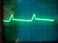
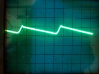
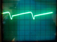
I have to admit it is nice to have a scope to use again, the VOM, logic probe and scope are very complementary. Not nice is spikey traces where I hoped for smooth waveforms!

If anyone has seen such wave shapes and has an idea, I'm definitely listening. It might help me decide where to start on component replacement in the power supply itself. I'll do a circuit diagram as soon as I can get it out of the chassis again.

With a bit of luck, I'll eventually get back to the Teletek!

Bruce

Voltages on the motherboard: +18.9V & -18.9V , and +8.85V.

AC component in the +18 is approx 20mV and is sawtooth shaped not sinusoidal. Faster rise than decay.
AC component in the -18 is approx 25mV and is sawtooth shaped not sinusoidal. Slower rise than decay.
AC component in the +8 is approx 22 mV. More like a short bump for the first 2/3 of the voltage swing, with a long decay for the last of voltage drop.

The floppy drive voltages are just about dead on and almost no ripple at all, so no worries there.

Pics; 20mV per division:
+16V
1.jpg

-16V
2.jpg

+8V
3.jpg
 
By the time the little bit of ripple makes it through the voltage regulators, it won't matter one bit. So, as long as the PSU levels are okay, let's drop the power supply thing.

Let's figure out if your Z80 is even running. Scope each of the address lines coming out of the Z80 and note any that show a static level. Similarly, look at the data lines on the Z80. Let's see if the darned thing is even ticking over.
 
By the time the little bit of ripple makes it through the voltage regulators, it won't matter one bit. So, as long as the PSU levels are okay, let's drop the power supply thing.
The Teletek has never complained, but two other boards of different manufacture did each burn up a trace at the card edge, and blew caps
Let's figure out if your Z80 is even running. Scope each of the address lines coming out of the Z80 and note any that show a static level. Similarly, look at the data lines on the Z80. Let's see if the darned thing is even ticking over.
Every Address line and data line is showing some sort of activity, pace is different for many. The GND and +5V show up clrearly, the clock is very different, but very hard to get a handle on. As for all the data and address lines, I'm not sure the synch circuits are so very great with this scope, and it may be holding out on me. But a pulsed voltage is unmistakable even if it drifts across the scope.

I'll try to get a thorough list of each pin's characteristics as soon as I can get the scope to lock on signals the way I remember them doing. I have the complete manual for the scope, -I have to reach an understanding with the thing.

For now, I'll assume scope is fine and I need more work.

Better data tomorrow, I hope, -time is tight.

Bruce
 
Back
Top