• Please review our updated Terms and Rules here

CBM 8032SK's blank screen

luismcv

Member
Joined
May 20, 2015
Messages
38
Location
London, UK
Hi.

Around 15 years ago I was given an 8032SK, with a keyboard and a 8050 dual disk drive. It was working back then. Or least the computer was; unfortunately I didn't have much time or interest back then and I never got to test the disk drive.

One day (after some months stored in a corner of an unused bedroom) I decided to spend some time testing the disk drives, learning how to use it, etc, but the the screen had stopped working, showing only an horizontal line on the center of the monitor.

Recently I decided to give it another go, but the problem now seems worse: the screen is completely blank. The computer still chirps though.

I'd like to get it working once again and I'd appreciate some help.

The main board is an Universal dynamic PET ass. no. 8032090.

What I have:

- Some digital electronics knowledge
- Very basic analog electronics knowledge
- Cheap multimeter (Tenma 72-7770)
- USB oscilloscope with 2 x 12MHz channels and a function generator (Velleman pcsgu250)
- Temperature controlled soldering iron
- A working VIC20 (although I'd hate to sacrifice it)
- 8032087 rev C board schematics from zimmers.net

What I lack:

- Proper soldering and, in particular, desoldering skills. Last time I tried to repair an LCD monitor I ended up damaging some lanes while desoldering some components. So I want to avoid desoldering and soldering unless necessary.

What I have tested so far:

- The computer chirps on power up.
- Tried to type ?chr$(7). No sound.

6545 readings:

- 40 VSYNC. No signal. This could explain the previous point, as I think that VERT DRIVE (and therefore VSYNC) is needed for the keyboard scan.
- 30 HSYNC. ±1.20V weird signal/ noise?
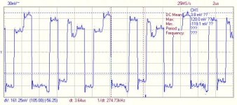
Image1.jpg
- 37-34 RA0-4 Low
- 33-26 DB0-7 Switching levels
- 25 /CS - High
- 24 RS - SL
- 23 phi2 - 1MHz
- 22 RW - SL
- 21 CCLK - 1MHz
- 19 CURSOR - H
- 18 DISP EN - H
- 17-4 TA13-0 - L
- 3 LPEN - L
- 2 /RES - H

6502 readings:

- 40 /RES - H
- 39, 37, 3 phi2-0 - 1MHz
- 38 SO - H
- 34 /RW - SL
- 33-26 D0-7 - SL
- 25-22,20-9 A15-0 - SL
- 7 SYNC - 0.333MHz
- 6 /NMI - H
- 4 /IRQ - H
- 2 RDY - H

I'm not sure what to do next.

Thanks!
 
I can't help with the diagnosis, but I do have a couple R6520 PIA chips here if you find you need them.
 
Hi,

So - you seem to have good oscilloscope skills (which is good news to try and identify what the problem is first - and then you can work out the best way to get it repaired once you are fairly sure you know what the fault is).

1. I would disconnect the monitor from the power supply and the pet logic first to prevent any (further) damage to the monitor. Only connect it back once you see healthy video and H & V synch signals.

2. I suspect that the PET is trying its best to boot up (signified by the initial BEEP) - but is then failing for some reason. With the lack of VSYNC I agree that the main logic board is probably faulty in the first instance.

3. Can you follow schematic diagrams?

4. After you have disconnected the monitor from the PSU and main logic board. Disconnect the logic board from the PSU and measure the AC voltages from the transformer with your multimeter. These should be within specification for your model.

5. Reconnect the main logic board and measure the DC power rails on the main logic board. These should be within specification for your model.

6. With the monitor disconnected - use your oscilloscope to measure the video and V&H synch signals again. The V&H synch signals should be a fairly healthy 5V (or so) logic signal. If not, you need to work your way 'backwards' on the schematic to identify where the signals change from +5V logic signals to something that is not there or strange readings (as identified by what you are seeing). I notice that you have already measured the signals on the pins of the CRTC - and I agree that the picture looks a bit strange that you are getting - too strange for my liking. How did you measure it (e.g. what oscilloscope have you got - what probes are you using and where have you actually got the probes connected to - especially the ground reference)?

See how far that gets you initially - and I will have a think where to go next.

Dave
 
Last edited:
It is interesting to note that pin 4 of the CPU (/IRQ) is high. This should be normally high - but should pulse low briefly on a regular basis. Can you confirm that it is always high please by (a) setting your oscilloscope timebase to a relative slow speed trace or (b) setting it to trigger on a low-going edge.

I suspect that the PET may be 'crashing out' before it gets to the point in the ROMS where it is initialising the CRTC - or the CRTC is actually faulty (especially if it was 'working' before but the scan on the monitor had collapsed). Is the CRTC socketed? If so - replace it.

You say that the CRTC /CS pin is high. If you have your scope probe permanently attached to the /CS pin of the CRTC when you power the PET up (or reset it if you have the reset button attached to the expansion port) do you see any activity on this pin or not. If not - the PET never attempted to address the CRTC and the fault probably lies elsewhere. If activity - it is most likely the CRT controller chip that is dead (or the PET is writing garbage to it...)

Just some further thoughts off the top of my head for you to consider.

There is another active thread currently on-going discussing trying to diagnose a faulty PET - it maybe worth reading that whole thread as some of what is presented will be applicable to your problem.

Dave
 
I can't help with the diagnosis, but I do have a couple R6520 PIA chips here if you find you need them.

Thank you very much for the offer. We might talk if I find I need the replace these and I can't source any others closer to here.
 
First of all, thanks a lot for your help daver2!

Hi,

So - you seem to have good oscilloscope skills (which is good news to try and identify what the problem is first - and then you can work out the best way to get it repaired once you are fairly sure you know what the fault is).

1. I would disconnect the monitor from the power supply and the pet logic first to prevent any (further) damage to the monitor. Only connect it back once you see healthy video and H & V synch signals.

Good point, thanks. I'll disconnect it straightaway.

2. I suspect that the PET is trying its best to boot up (signified by the initial BEEP) - but is then failing for some reason. With the lack of VSYNC I agree that the main logic board is probably faulty in the first instance.

That's what I think. Do you know by any chance where I can find a detailed description of the boot sequence, in which order is everything initialised and at what point the chirp happens?

3. Can you follow schematic diagrams?

Yes, I can. No problem with that. I even got to use Eagle and Orcad many years ago to design simple circuits when I was in uni.

4. After you have disconnected the monitor from the PSU and main logic board. Disconnect the logic board from the PSU and measure the AC voltages from the transformer with your multimeter. These should be within specification for your model.
5. Reconnect the main logic board and measure the DC power rails on the main logic board. These should be within specification for your model.
6. With the monitor disconnected - use your oscilloscope to measure the video and V&H synch signals again. The V&H synch signals should be a fairly healthy 5V (or so) logic signal. If not, you need to work your way 'backwards' on the schematic to identify where the signals change from +5V logic signals to something that is not there or strange readings (as identified by what you are seeing).

I'll check these soon, probably during this weekend.

I notice that you have already measured the signals on the pins of the CRTC - and I agree that the picture looks a bit strange that you are getting - too strange for my liking. How did you measure it (e.g. what oscilloscope have you got - what probes are you using and where have you actually got the probes connected to - especially the ground reference)?

A Velleman pcsgu250 usb oscilloscope, using the probe it came with at X1 (60MHz, 23ns rise time, 1M input resistance, 46pF capacitance according to the specs). As reference I'm using a few GND pins in the J4 memory expansion connector. I got those reads in AC mode, in DC mode I didn't get anything.
 
It is interesting to note that pin 4 of the CPU (/IRQ) is high. This should be normally high - but should pulse low briefly on a regular basis. Can you confirm that it is always high please by (a) setting your oscilloscope timebase to a relative slow speed trace or (b) setting it to trigger on a low-going edge.

I'll recheck and let you know.

I suspect that the PET may be 'crashing out' before it gets to the point in the ROMS where it is initialising the CRTC - or the CRTC is actually faulty (especially if it was 'working' before but the scan on the monitor had collapsed). Is the CRTC socketed? If so - replace it.

I'm afraid it's not socketed :/

You say that the CRTC /CS pin is high. If you have your scope probe permanently attached to the /CS pin of the CRTC when you power the PET up (or reset it if you have the reset button attached to the expansion port) do you see any activity on this pin or not. If not - the PET never attempted to address the CRTC and the fault probably lies elsewhere. If activity - it is most likely the CRT controller chip that is dead (or the PET is writing garbage to it...)

Problem is that, obviously when I switch it off it goes down, so it's not easy to see, but I think that once powered up, it doesn't go down again. I'll try to attach some kind of reset switch (I guess this is just a matter of temporary grounding pin 19 of J9?) and recheck.

Just some further thoughts off the top of my head for you to consider.

There is another active thread currently on-going discussing trying to diagnose a faulty PET - it maybe worth reading that whole thread as some of what is presented will be applicable to your problem.

Dave

Yes, I've been following it, and I also had a look at a couple of other older threads... I'll re read again for more ideas.

Cheers!
 
Well, I found some time tonight to measure a few things.

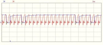
But first, I've just realised I made two errors when I said "30 HSYNC. ±1.20V weird signal/ noise?" in my first post. That should've been pin 39 and ±0.12V. So it's just a ±0.12V ripple that, at least tonight, after totally disconnecting the monitor I'm finding pretty much everywhere. I didn't want to plug in the monitor again, so I'm not sure if that has something to do, or I wasn't careful enough the last time.

Anyway, the measures I took tonight:

*** AC from transformer, unplugged from both monitor and main board.
Monitor supply: 22V
Blue wires: 16.6V
Black with either brown one: 8.9

*** Power in main board:
+9 unreg measured from J11: 11.18V
-9 unreg from J10: -12.32V
+16 unreg from J10: 21.40V
+5 from 6545, 6502 and UA19: 5.00V
-5 from UA19: -5.10V
+12 from UA19: 11.99V

so the unregulated voltages seem a high, but I'm not sure if this is within the specifications. Once regulated they seem fine, but they might be putting too much stress into the voltage regulators?

*** Voltages in signal connector to monitor (J7)
1 /VIDEO: 4.98V
3 V. DRIVE: 3.45V
5 H. DRIVE: 4.98V

I've rechecked with the oscilloscope, and V. DRIVE is fixed at 3.45V (±, again, a small ripple)

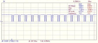
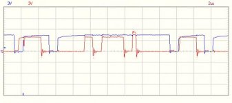
*** Using a descending flank trigger (something that didn't even cross my mind the other day) I've seen that the 6545 /CS is being pulled down several times after powering up. And I've rechecked a few times again but forcing a reset of the processor by shorting pins 1 and 40:

6545cs.jpg

*** I've rechecked /IRQ pin of the processor, this time using triggers, and no, it's not pulsing, it's always high. What should be requesting an IRQ? The PIAs I guess? But even with no devices connected to the IEEE-488 interface and no keyboard scan due to no Vertical Drive?

If /IRQ should indeed be pulsing, then probably there is something else wrong. If not, then my guess is that the 6545 is damaged or that it's being incorrectly initialised. Something is being sent to it, as /CS fluctuates, but how can I check what's being sent to it without a logic analyser? I guess I could fix /CS to one channel of the oscilloscope to control the trigger and use the other channel to record one by one all the data lines, R/W and RS after a reset and hope that the timings don't differ much between each reset. But it sounds like a tremendous task and very error prone. I have an Arduino, but I don't think they're fast enough.
 
It helps to prove what it can't be first and then home in on what it can be...

I start off by making sure that the power supplies are all OK and that they are in specification (from a DC rail voltage level first - and then do not have any high frequency noise or ripple on them second). You can use a multimeter for the first test (dc) but you have to use an oscilloscope for the second test - so you may as well use an oscilloscope throughout since you have one. You would be amazed at the number of problems there are related to out-of-spec power rails (and they just appear to the user as general unreliability).

J9 pin 19 is the /IRQ line - so it is not that for reset.

J4 pin 22 should be reset - or you can ground C51 in the power on reset circuitry (see http://www.zimmers.net/anonftp/pub/cbm/schematics/computers/pet/univ2/8032087-01.gif).

1.2V of 'noise' on HSYNC from the CRTC is excessive. You certainly need a good 'ground' for your oscilloscope lead. What happens if you probe directly the +5V and the GROUND rails of the motherboard with the scope? The ground rail should be pretty close to 0V (!) If it isn't this indicates that your measurement technique needs looking at first - as it is giving us false readings. The +5V rail should be 5V +/- 0.25V DC with a small amount of switching noise and/or 100 Hz ripple. Use the scope on DC to measure the DC voltage level and AC to measure the noise and ripple.

Pity the CRTC is soldered in. Since you are not into desoldering - we need to identify if it is the CRTC before looking to exchange it. If the PET is not accessing the CRTC on start-up then it is probably not the CRTC to start with.

You may also like to consider using PETTESTER. This is a downloadable bit of test code that can be burnt into an EPROM and exchanged for one of the ROMS on the mainboard. This provides some simple checks. If PETTESTER runs - then this can be used to checkout the rest of the system more easily. If not - there is something fairly fundamental wrong...

There is also PETVET as well - this is a separate board that plugs into the 6502 CPU socket and can replace onboard ROM and RAM.

Have a look at these two items on the internet.

Dave
 
(I hope the new user moderation period ends soon because it makes very difficult to have a fluid conversation)

Yes, you're right, pin 22 of J4. Sorry, I should be more careful and double check things before posting. Anyway, as you'll see when my post from last night is approved, that temporarily I just used a piece of wire and pin 40. If I keep needing to reset frequently (and most probably I will) I'll prepare a proper solution with a switch connected to the expansion connector's pins.

Sorry again, but the noise or ripple was really ±0.12V (I already wrote about this, but once again you haven't seen it yet because of the moderation). I don't know what produces it, but it's frequency is much higher than 100Hz, in the order of the 250kHz.

Unfortunately I don't have any EPROM writer. I'm afraid repairing this is soon escalating to a level out of the reach of the kind of equipment I have.

I saw about the PETVET in other threads. It seems useful for testing and even as a final solution in some cases (although in my opinion, as it replaces a good part of the PET circuitry that would defeat the purpose of actually repairing the machine and ***exaggerating, don't take me seriously*** one might just as well replace everything with a Rasperry Pi and a CBM emulator). In any case, if this actually a broken CRTC, the PETVET wouldn't solve anything in my case (apart from helping diagnosing this).

At this point I think that my "least bad" option might be replacing the 8545. But where can I find this in the UK?
 
id download the pettester and burn it on to rom once your sure the power is ok.it fits in the kernel socket (if you have a socket that is)

this will enable the crt and tell you if the CRT controller is working and whats happening on screen - if anything

this will help hugely in finding problems , as for Petvet .. great bit of kit but try Dave at Tynemouth software hes somewhat quicker to respond and he has new PCB's in stock (28.5.11)

good luck.

mike
 
A Velleman pcsgu250 usb oscilloscope, using the probe it came with at X1 (60MHz, 23ns rise time, 1M input resistance, 46pF capacitance according to the specs). As reference I'm using a few GND pins in the J4 memory expansion connector. I got those reads in AC mode, in DC mode I didn't get anything.

From the scope photo, with a 1X probe, you were measuring only noise on the Horizontal. Use DC mode and 2V/div since the PET main board is all TTL (including video data), and know where the ground reference is.
 
Problem is that, obviously when I switch it off it goes down, so it's not easy to see, but I think that once powered up, it doesn't go down again. I'll try to attach some kind of reset switch (I guess this is just a matter of temporary grounding pin 19 of J9?) and recheck.

daver2 is correct, the RESET is on J4-22. The CRTC is initialized right after power up with 17 chip selects to load its registers, and never addressed again so you have to catch it right after power up with logic probe or scope set it for single trigger. A reset pushbutton will help with this and will save the power supply. I suspect the CRTC is not being initialized due to problem with running the code and is probably OK.
 
I've just seen that you can now buy very cheap logic analysers on ebay, and even a reasonable cheap multipurpose programmer/tester for lots of different eproms and ICs. It's amazing how much the price of these things has dropped in the last few years; most probably thanks to the market that arduinos/rasperries/etc have opened.

So for the moment I've ordered a logic analyser and we'll take it from there. Hopefully it will arrive in a week or two.
 
daver2 is correct, the RESET is on J4-22. The CRTC is initialized right after power up with 17 chip selects to load its registers, and never addressed again so you have to catch it right after power up with logic probe or scope set it for single trigger. A reset pushbutton will help with this and will save the power supply. I suspect the CRTC is not being initialized due to problem with running the code and is probably OK.

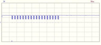
I can count in mine 18 groups of two (one for writing the Address register and one for writing the actual register, I guess). Maybe of the 18 is just a read? I'll find out when I get the logic analyser.

6545cs2.jpg
 
Are all 6545-1 variations compatible with the CBM 8032? Will a Synertek SY6545-1 work fine? Are the 6845 in all their variations suitable too?
 
Are all 6545-1 variations compatible with the CBM 8032? Will a Synertek SY6545-1 work fine? Are the 6845 in all their variations suitable too?

Well done with the capture of the CRTC initialization. It is correct so it appears that the 6545 CRTC is broken although it could be a problem with the data on the bus or with address bit 0. Can you capture any of those signals along with the chip select?

Any of the 6545 or 6845 devices should do. There are subtle enhancements on some of them but the PET does not use any of them.
 
Well done with the capture of the CRTC initialization. It is correct so it appears that the 6545 CRTC is broken although it could be a problem with the data on the bus or with address bit 0. Can you capture any of those signals along with the chip select?

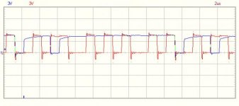
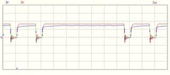
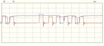
Well, there is definitely some activity:

/CS vs RS (AB0)
csrs.jpg

/CS vs R/W (BR/W)
csrw.jpg

/CS vs E (B02)
csphi2.jpg

And some data lines (DB0 and DB3)
csdb0.jpg
csdb3.jpg

But I think I'll wait until I receive the logic analyser and can see what data it's receiving.

Anyway, as it's looking like I might end having to replace the 6545 I've ordered some DIP40 sockets (that might also come handy to make a NOP generator if I need it).

I see some cheap 6x45 on ebay I'll get it too.

And I want to start looking at proper desoldering. What are the safest technique and materials for desoldering DIP ICs?
 
Anyway, as it's looking like I might end having to replace the 6545...

What are the safest technique and materials for desoldering DIP ICs?

These signals look good. The analyzer may tell more, but right now it looks like the CRTC is kaput.

Techniques differ, but for me, I do not like to risk overheating the PCB. So on 40 pin packages, I would sacrifice the chip, and cut off all 40 legs close to the chip body. Then using a soldering iron, needle nose pliers and desoldering braid, desolder and remove the legs one at a time. This should minimize heat to the circuit board and traces. Other have good success by using a solder sucker to remove the solder from all the pins and then removing the part intact. If you have a good touch and let the board cool off as necessary, that should work also.
 
I use patience and plenty of experience and almost never cut pins. I believe most anyone can do this, but I don't have the patience to write up instructions tonight. I have written such instructions somewhere else on the forum but wouldn't know where to begin to find them at this point.

As Dave says you could do it either way. Either way though in my opinion you need patience and good soldering technique, which can be learned very quickly I think.

One thing I would avoid is heat guns and high power soldering guns.
 
Back
Top