• Please review our updated Terms and Rules here

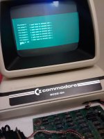
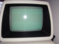
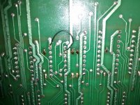
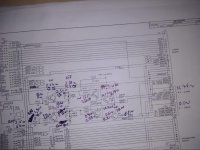
CBM 8032SK's blank screen

I don't know much about Arduino, but if it can drive TTL, it should work just fine.

If I can do it with one of these,
attachment.php

I would expect an Arduino would work just fine. (That machine uses 9V logic, shh! don't tell anyone!)

Yes, you assert logic levels by connecting them directly to Vss and Vcc. The only time you don't is when something else is, without a pullup resistor. Your CS example is where you don't want to do this, without first disconnecting the other output.
 

Attachments

  • 6-04-15-Supercell-Tornados-Simla-Colorado-3k.jpg
    6-04-15-Supercell-Tornados-Simla-Colorado-3k.jpg
    14 KB · Views: 1
The only time you don't is when something else is, without a pullup resistor. Your CS example is where you don't want to do this, without first disconnecting the other output.

Wouldn't the internal pull-up resistors of the NAND protect it against a short circuit if I pull down its output when it's high? I can see a problem in the opposite case, pulling-up a low output, but that shouldn't be the case. I'll measure this output when I remove the CPU, but it should be high, or I could always force it to a high state by pulling down AB7, which will bring BA7 to low too.
 
Well, I've reading about how TTL works and found that those resistors are only 120 Ohm, so they offer some protection against short circuits (short circuits can actually be inherent to TTL during state transitions where for a very short period both transistors might be on) but the IC might overheat and get destroyed if the short is kept for too long.

As a matter of fact, the 74LS10 datasheets warn about this: "Note 1: Not more than one output should be shorted at a time, nor for more than 1 second."

So, as far as I make sure the arduino output is high before I connect it to /CS and the low pulses are short enough, I should be fine.
 
I missed your previous post but I'm glad you found the information you needed. What I wonder is why affect /CS directly? I don't have the schematic in front of me , but couldn't you use the Arduino to generate an address that causes /CS?
 
I missed your previous post but I'm glad you found the information you needed. What I wonder is why affect /CS directly? I don't have the schematic in front of me , but couldn't you use the Arduino to generate an address that causes /CS?

No worries. I can't, at least not directly from the arduino, it doesn't have so many outputs (14). But as I mentioned before I could hardwire AB8-15 and leave the arduino to control AB7.

I want to test it both ways - by controlling /CS directly and by generating the address that enables it - to compare the results. If I see corruption in the data lines in both cases, then the problem is most probably the CRTC. If I don't see corruption when controlling /CS directly but I do when generating the address, then most probably there is something wrong with the address lines that are enabling the outputs of some other IC when they shouldn't.
 
Last night I removed the CPUs of the VIC20 and the CBM, put them on additional sockets to make it easier to insert and remove them again without having to worry too much about their legs and I swapped them. I guess that both CPUs are fine, the CBM's worked in the VIC and the CBM still doesn't work with VIC's.

So I left the CBM without the CPU and using a socket, a breadboard and some dupont wires I connected it to the Arduino in this way:
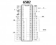
arduino.jpg

A[15:12] = 1110 to obtain /SEL E = /IO
A[11:8] = 1000 to get x8xx

Then I tried to initialise the CRTC from the Arduino. No success, I couldn't get any sync signals. As far as I know I'm sending the data in the right way. This is a capture of part of the communication, from the CRTC's pins:
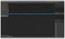
Screen Shot 2015-06-23 at 22.36.41.jpg

Looks fine to me.

(edit: I don't know why the forum shrinks my snapshots so much; I've uploaded it to my Drive shared folder: https://drive.google.com/folderview...ZiWEswcFplbXNhWlp1Z3h0WmtPd2E0cG8&usp=sharing)

I didn't observe any data corruption though, like I did with the CPU/ROM the other day. I don't know if it's because the Arduino can generate stronger signals or why. In theory I'm doing pretty much what the CPU does. Am I missing something? I checked the clock on pin 21 of the CRTC and it was receiving it fine, as expected, as it doesn't depend on the CPU for anything.

Even though I didn't get any corruption by indirectly generating CS from the address lines, I also gave it a go to controlling CS directly. I changed A[15:12] to 0000 so not /SELx line was enabled (which also gave me a high /CS by default), I inverted CS in the Arduino's code and I connected it directly to pin 25 of the CRTC instead of A7 in the CPU's socket. Same disappointing result: no sync signals.

Then, a few seconds after I switched the CBM off to disconnect the Arduino and reinsert the CPU (I wanted to make sure the corruption was still happening with the CPU without touching any of the connections to the logic analyser after the last tests with the Arduino) something in the power supply side explode:
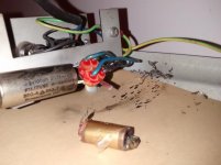
IMG_20150623_214819.jpg

Somewhat funny that it happened after switching it off and not while powered or while switching it on.

I'm not sure what this is and what to get to replace it. From the printed units, it seems it's some combination of capacitors (3?) and inductors (2?) all in one? I can't see if in the schematics of the standard 8032 here http://www.zimmers.net/anonftp/pub/cbm/schematics/computers/pet/8032/8032051-3.gif. But my SK's transformer isn't wired exactly like in those schematics either. So it's probably using another newer revision.

So, party poppers apart (once I fix the damage) and unless someone thinks I did something wrong while trying to initialise the CRTC with the Arduino, I think that I'll have to desolder the CRTC, solder a socket and try with the 6845 that I got, as there might be something else wrong, but apparently the 6545 isn't working either.
 
Thanks Tom. That gave me some key words to do a search.

I also now realise that it's indeed represented in the power supply's schematics as part of the "power connector". And it's connected before the fuse and switch, so no wonder it exploded while the computer was switched off.

Anyway, it seems that it can just be removed, so I'll probably do that for now. If I manage to fix the video I might later consider resourcing a proper replacement.
 
*** Short version ***

I replaced the 6545 with the 6845 and it's working now. Today I've adjusted the background brightness and the height of the image. But it's a bit displaced to the bottom-right. I don't think it's possible to adjust its position, is it?

IMG_20150629_202953.jpg

I've also tested the datasette ports today with my VIC's. On port 1 the motor doesn't work and each time I press or release PLAY the screen looses sync for a sec. I guess it's one of the transistors between the PIA and the port; tomorrow I'll do some voltage measurements. But anyway, as port 2 works fine, I'm not too worried about this and I might not even bother to fix it.

Next, sometime this week, testing the disk drives.
 
There's always a way to adjust the position. :D

You can try adjusting Horizontal and Vertical Hold a little bit.

If that doesn't work, and there just aren't any positioning pots, you can
1) Adjust the position of the yoke
2) Figure out where a DC offset might be coming from and eliminate it
3) Inject your own DC offset
4) Tack on some very carefully placed magnets.

So far as the K7/CRT interaction, maybe you have a power supply problem yet. Or a shorted power transistor, or even a shorted PIA output. In fact, I'd check the PIA first.
 
*** Long version ***

A few days ago I realised that I had the logic of RS inverted in my arduino's code, so I wanted to fix it and give it another ago. But this time I tried with the spare 6845 in a breadboard, connected directly to the arduino. I connected the CCLK input to another output of the arduino that, after the initialisation, started to switch (I guess that you need a clock to get any sync, refresh and raster signals).

Anyway, I couldn't make it work. Either I'm missing something else or the CRTC won't output anything if the clock is not within some range (the UM6845 and MC6845 datasheets don't specify a maximum period or minimum frequency, but the MOS6545's does specify a maximum period of 40us and the arduino is too slow for that. Now I've just realised that I could have used one of the PWM outputs, that can go up to 16MHz.

I was pretty much at square one, not knowing if the CMB's 6545 was bad or not. So before embarking myself in the task of desoldering it, I though it was worth it to recheck again what it was receiving, which is what I wanted to do the other night just before the mains filter burst. And this time I didn't see any corruption! I checked the LSB and MSB and both were fine. I guess that re-seating the 6502 the other day might have solved it, or I somehow I managed to screw my several previous other tests. Still no signals though.

So I got the 6845, piggybacked it, switched the computer on and...

I got hsync and vsync!! No video signal though (I guess some of the MA o RA lines weren't making a good contact). Anyway, enough to warrant a painful desoldering session.

I first tried with desoldering braid. I don't know if it's because it was a very cheap one or I'm just useless, I couldn't remove pretty much any solder with it. I even tried adding additional flux.

Then with an old de-solder pump that I had. And although I could get most of the solder out of most of the holes, some of them resisted. I tried to add extra solder and try again a few times until I got tired.

So considering that the 6545 was most probably broken, and that anyways they're not that rare, I went the cutting-the-pins way. Still a pain because I didn't have the right tool but after a while I cut the IC loose and removed the legs one by one.

Leaving the holes clean was tough, until I found out about a trick using a pencil lead.

But at last I managed to solder the socket. I inserted the 6845, connected everything and bingo!

*** commodore basic 4.0 ***

31743 bytes free

ready.

:)
 
There's always a way to adjust the position. :D
You can try adjusting Horizontal and Vertical Hold a little bit.

I tried V LIN, is that V hold? It didn't have much effect on the vertical position.

If that doesn't work, and there just aren't any positioning pots, you can

HEIGHT, V LIN, WIDTH, BRIGHT, SUB BRIGHT and FOCUS. Those are all that I can see.

1) Adjust the position of the yoke
2) Figure out where a DC offset might be coming from and eliminate it
3) Inject your own DC offset
4) Tack on some very carefully placed magnets.

1) Is it easy to do? What are the chances of ending with an even more misaligned screen, probably not even level anymore?
2,3) Is it easy to check if I even have an offset?

So far as the K7/CRT interaction, maybe you have a power supply problem yet.

The other port works fine. Wouldn't it be affected too in this case?

Or a shorted power transistor, or even a shorted PIA output. In fact, I'd check the PIA first.

I'll start by the PIA and follow all the path to the port then.

I'm not so concerned about the actual port not working, but if there is a short somewhere, it could cause further damage later, right?
 
I never remembered to mention that this computer seems to have two patches/fixes, either from the factory or most probably done during its lifetime in that workshop it came from.

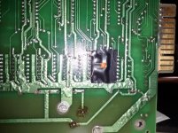
One is what I guess it's a resistor between pins 9 and 15 of the UA19 4116. Pulling up /CAS? What for? Making sure it stays high until UA17 pulls it down because either UA17 or UA19 itself are damaged and cannot keep it high by themselves?

IMG_20150629_190229.jpg

By the way, I've just realised in the picture that the soldering points of the power regulator seem a bit burnt. Not sure if by someone that replaced it or by its own heat???


The other one puzzles me even more. A short between pins 7 and 9 of the UE7 74LS10. That's forcing the output of that NAND (pin 8) to always HIGH. And that goes to the D input of the UE1 flip-flop, which will always store and output a 1 too, effectively disabling one of the two signals by which /RAS0 is generated. But to be honest, I don't really understand what each part of the Master Timing circuit does.

IMG_20150629_190200.jpg
 
One is what I guess it's a resistor between pins 9 and 15 of the UA19 4116. Pulling up /CAS? What for? Making sure it stays high until UA17 pulls it down because either UA17 or UA19 itself are damaged and cannot keep it high by themselves?

I suppose, but I would take it out and make sure you get a good pulse on /CAS0.

The other one puzzles me even more. A short between pins 7 and 9 of the UE7 74LS10. That's forcing the output of that NAND (pin 8 ) to always HIGH. And that goes to the D input of the UE1 flip-flop, which will always store and output a 1 too, effectively disabling one of the two signals by which /RAS0 is generated.
This would keep /RAS0 always asserted. I would think this would mess up the refresh of the dynamic memories. Take it out.
 
I tried V LIN, is that V hold? It didn't have much effect on the vertical position.
That is Vertical Linearity, which adjusts how linear the deflection path is. You will likely need to readjust it now. If you put a series of horizontal lines on the screen, "_" characters, you can measure between them. Adjust the control till the distance is as close to equal as you can get it.

HEIGHT, V LIN, WIDTH, BRIGHT, SUB BRIGHT and FOCUS. Those are all that I can see.
There is probably V-HOLD and H-HOLD, somewhere, unlabeled. They may be slug-tuned inductors rather than potentiometers.

1) Is it easy to do? What are the chances of ending with an even more misaligned screen, probably not even level anymore?
Yes, it's easy to do. The chances of ending even more misaligned are pretty good, but you can realign it however you want. It does take a bit of patience to do this.

2,3) Is it easy to check if I even have an offset?
Yes, with an oscilloscope, with DC coupling. I don't necessarily recommend this, unless you are very familiar with sweep circuits. You really don't want to attach your scope directly to the deflection coils where there is a possibility to damage your scope from high voltage pulses, in the 4kV+ range.

The other port works fine. Wouldn't it be affected too in this case?
Probably not, but I don't have the means to study the schematic at the moment. I do think separate outputs and power transistors are used.

I'm not so concerned about the actual port not working, but if there is a short somewhere, it could cause further damage later, right?
Maybe. Actually, it would be nice if the short would burn itself out. That would make it easier to find. But, this doesn't always happen.
 
Last edited:
I suppose, but I would take it out and make sure you get a good pulse on /CAS0.

I've checked with the resistor still in place and I get a good pulse. I think that I'm going to assume that whoever did this did it for a reason, and I'm going to leave it. At least for now.

This would keep /RAS0 always asserted.

Actually not, I checked with the oscilloscope and a clear signal (pin 13) that comes from the shift register UE3 switches periodically, clearing the bit. So maybe less frequently (I can't remember and I didn't wrote down the clear's frequency, but coming from the shift register, it must be 1MHz), but this part of the RAS0 still flips. By the way, I think the schematics is wrong: it shows inverted inputs on pins 8 and 9, but, afaik, this is just a normal NOR (74LS02).

I'm not sure what to do, as before, I'm tempted to think that this has been patched for a reason. On the other hand, every now and then something seems to go awry, usually during boot up, and it shows me the machine language monitor. Could be related if because of this patch the memory isn't being refreshed frequently enough?

If I remove it, I can't just remove it. I need to join this pin 9 again to pins 10 and 11, as the trace was cut.

Does anyone understand what each of the two parts of the RAS0 timing circuit try to accomplish and what this patch might be doing?
 
Last edited:
That is Vertical Linearity, which adjusts how linear the deflection path is. You will likely need to readjust it now. If you put a series of horizontal lines on the screen, "_" characters, you can measure between them. Adjust the control till the distance is as close to equal as you can get it.

Nah, when I touched it, as I wasn't sure what its purpose was, I made sure I left it again in the same position it was. Lines are still parallel.

There is probably V-HOLD and H-HOLD, somewhere, unlabeled. They may be slug-tuned inductors rather than potentiometers.

Can't find any, neither in the board nor the schematics. And all the other options seem a bit too much trouble for the benefit.
 
Regarding the tape connector, I've been measuring both AC and DC components at several places of both tape 1 (which doesn't work) and 2 (which works) while their corresponding motor signal should be on. I also measured the VIA and PIA pins when OFF.

This is what I got:

IMG_20150708_223741.jpg

My guess it's the transistor on pins 12-14, that should invert the signal from the PIA, which is broken. Whether this could cause more problems apart from the motor signal not working escapes to my knowledge of analog electronics. Should I try to replace the Q2T2222 or at least try to disable this part? Or should I be safe as far as I don't use this port?
 
Back
Top