• Please review our updated Terms and Rules here

Heathkit h-11a and h27 disk drive

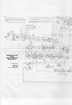
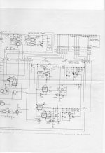
I have noticed that early in this thread, user kyeakel worked on repairing the power supply on a Heathkit H-11. Does anybody know where I can find a copy of the schematic for the Heathkit H-11 power supply.

I do not have either schematic, but I do have some info that may help you find them. Along with my H11/H27 I received a copy of the H11 Operations Manual (Heathkit P/N 595-2019). Mine is apparently a copy of a copy dated 1977. A number of circuit board x-ray views are included on pages 5-18 through 5-22. Based on other original Heathkit documents I have, these were multicolored drawings showing the layout and traces on both sides of the respective circuit board. Unfortunately the color to B/W copying process rendered the one I have for the Power Supply Circuit Board on page 5-22 a mostly black blob. No help there. The table of contents says that the "Schematic" is supposed to be a fold-in following page 5-23. This probably, based again on other Heathkits I have, would have included the schematics for the H11 and the power supply but not any optional boards. My copy came with no schematics at all.

Not much help but maybe better than nothing.
 
Kipp --

I just bought an H-11A (no manuals) and, separately, two H-11-5 async cards (with manuals). No floppy card that I know of, and only 4kw of memory. Do you have, or have you found, an archive of scanned manuals somewhere for the H-11?

Also, I was thinking of getting an additional memory board. I found a page in an old Motorola semiconductor data book with a memory board cross-reference. There are a few alternatives to the MSV11-xx (M8044-xx) boards, but they're in both 16-bit and 18-bit variants. I'm guessing the 16-bit version is required, but I wanted to check that with someone first. What's the maximum memory for the H-11? 32kw?

Thanks!
 
Rich,

I have a fairly complete set of original documentation, so I have not gone looking much on the web. Do you have the older style CPU that is full width in the card cage? I think that has 4kw on it. Mine are the newer 1/2 cage (2 connector) style where the CPU and the memory are separate. I have 1 CPU, 2 16kw memory cards, a 8 port serial card, and a floppy controller in one of my machines. The other has 1 CPU, 2 16kw memory cards, a serial card H-11-5, and a parallel port card. I think I have memory cards that have an M# on them, I'll have to check when I get home.
The unit is a DEC PDP 11-03 clone, so some info from bitsavers.org is useful. If there is something specific you need, let me know and I'll scan it.

Kipp
 
Kipp --

Per UPS, it should be here tomorrow but my understanding is it's a half-width CPU card, so it would be of the newer variety. I downloaded the DEC-issued LSI-11 manual from Bitsavers (600+ pages; haven't read it yet), but I'm really looking for the Heath-specific manuals (assembly and schematics) more so than the DEC manuals...although I confess I don't know exactly what was originally distributed with the unit when purchased. I'm just trying to pull together as much as I can so I can check the unit out properly and make sure it's configured for testing.

Thanks!

Rich
 
All --

I received the H11 yesterday and there's some good news and some bad news. The good news is that it's actually better configured than I thought -- it includes two 16kw Heath memory boards and the H11-5 SLU. So, that's good.

The bad news is that it had a rough trip from Wisconsin. It looks like it was dropped more than once and both side panels are broken. Many of the holes that contain the threaded screw inserts have cracked, so the sides float on the chassis. I'm considering making exotic wood sides for it as a replacement.

This unit is a two-switch unit with a third SPST toggle switch drilled into the metal. This switch connects to two points on the power supply board. I do not have the manual for the system enclosure so I don't know what the switch is for. Based on the schematics posted above (which is for the three-switch version), I don't think it's an added LTC switch. So, I could really use a scan of the main manual.

I plan on working on qualifying the power supply this weekend. Lots of fun!

Rich
 
All --

As a follow-up, I spent some time over the last week working with the H11. It's in good shape operationally, which is good news. I can communicate with it using the ODT, and I installed (but haven't tested) the second SLU for use with a TU58 emulator. The serial connectors and parts are on order so I should be able to get the TU58 working in a week or so.

As far as restoring the case, I've been able to epoxy the threaded inserts into the side panels, so that's good. I've also embarked removing the flat black paint from the front panel. That hasn't been as successful. In fact, I'd love to get replacement/spare plastic badges and the plastic switch legend so that I can totally strip the metal and repaint it. For now, I have them masked but I worry about ruining them in the restoration process.

Also, I'd like to know if anyone has found a suitable paint match for "Heathkit Gray" or whatever the color is called.

That's it for now. Thanks!
 
All --

Following up on this thread, here are some updates:

* I stripped and repainted the metal front panel. I got off as much of the old flat black paint without damaging the plastic switch labels, gave it a quick sand,
and then spray painted it. Rust-Oleum seems to have a suitable paint color that approximates the Heath color. It's called "Matte Ice Gray with Primer" (#282818).
I followed it up with a coat of Rust-Oleum gloss and it looks pretty good. A few pictures are on my Web site.

* I was able to locate a copy of the original H11 assembly manual, and I also got an H11-2 parallel board and manual. Documents are scanned and will be posted
this weekend.

* I have the second SLU working with the TU58 emulator and I can boot XXDP v2.6 with no problems. I found instructions on how to get RT-11 working (basically
booting an RK05 target with SIMH and changing the boot device to DD, then loading that image into TU58EM). It's supposed to work, but I haven't gotten it to do so.
If anyone has actually done this, please send me a PM -- I must be doing it wrong. TU58EM shows activity but it won't boot to RT-11.

For references, this is the process I used: http://www.avitech.com.au/pdp-11-03/make-tu58-rtv4-image.html

That's it for now.
 
Last edited:
All --

This weekend I was able to successfully run RT-11 v4 and v5.03 on the H-11 with the TU58 emulator. The problem I was having was related to a broken interrupt chain. The slot numbering on the H-11 starts in the upper-right (which has a RAM card in my system). I assumed it started with the CPU which on my system is in slot 2. So, I had the SLU in the wrong slot to preserve continuity. It wasn't until Malcolm mentioned the bus continuity that I checked the H-11 manual I received this week that I realized that I had the slot numbering wrong.

As a result, RT-11 was barfing half-way through the bootstrap process, presumably when enabling interrupts. Once I moved the card one slot to the right, it worked just fine.

Thanks to Malcolm Macleod and Mattis Lind for the help with getting this running! There's a write-up about it on my site.

Rich
 
Last edited:
I've PM'ed a few folks but thought I'd post my request here as well. My H27 has a bad 2716 EPROM on the Z80 controller board. Although the code has many calls and branches to locations between 400h and 7ffh, that region shows as a duplicate of the lower 1k and none of the target entry points make sense in that context. I've reached the sad conclusion that the top address is either stuck low or disconnected internally.

Can someone with a working H27 please grab an image of this part so I can blow a new one and get this going again?

Update: I finally figured out that the TMS2716 has a different pinout from most of the other 2k EPROMs. Once I came to my senses and used the appropriate adapter my programmer was able to read a complete image. Currently in the process of disassembling the Z80 controller firmware to the point where I can poke intelligently with an ICE.
 
Last edited:
Hoping to get an image of these during VCFSW from my working H27 if I can. With any luck, I'll see about handing it off to Bitsavers to archive once I've got it.
 
FWIW, there are more than just the one EPROM for the Z80 on the controller board -- there's two other ROMs as well, according to the WH27 schematics.
 
Back
Top