• Please review our updated Terms and Rules here

A pair of Pets - Preparing to test after perhaps 40 years unused

In cases like this, it is back to the NOP generator to work out if there is anything wrong with the address bus or address decoding...

Dave
 
back to the NOP generator
OK. Will do but will be tomorrow night for me now.

The extra thing I just realised is that the CS is only passing back to the UD7 when it's my 'new' Kernal in UD6. I did lots of resets and it's consistent. Perhaps at least we've established that the original Kernal had gone bad.

I've not run the logic analyser today, but just using the scope I can see a brief bit of UD6 CS activity on reset, then to UD7.

Putting the real UD7/EDIT back in, I get CS oscillating on both UD6 and UD7 - nothing on UD8/9/10.

Still nothing on the display drive lines.
 
It is probably the case then that the 'old' Kernal ROM (or at last part of it) is toast.

Can I ask that you dump the ROM and post it here. I can have a look at it. There are only a few instructions of importance.

If the 'new' Kernal ROM is getting us into the EDIT ROM, that is good.

After that, we need to see why the screen is not being displayed.

Can you remind me what the part number of the PCB again is please?

Either way, you should observe some brief activity on the /CS line of the CRTC when you reset the PET. This is PETTESTER programming the CRTC.

Dave
 
Last edited:
No problem. I am going away on a business tip for a few days myself.

UB13 is the CRT controller on a univ2 board.

Check pin 24 (BA0) for signs of activity after a reset.
Check pin 23 (E) for a 1 MHz clock.
Check pin 22 (BR/W) for activity after a reset.
Check pin 21 (/CLK1) for a 1 MHz clock.
Check pin 2 (/RES) for an active low RESET signal.

Check pin 25 (/CS) for signs of activity just after a reset. This signal should pulse 16 or 17 times immediately after a RESET as PETTESTER initialises the CRT Controller.

The data lines of the CRT Controller are driven directly from the CPU so (unless there is a break or bad connection) they should be OK.

Dave
 
No CS ever on the CRTC. I zoomed right in, nothing.

The reset here is a soft reset & the real EDIT ROM in this time. I'll get the NOP going and see what's happening on/upstream of UE13


8032-CRTC-CS.png
 
It is tempting to use logic analyzers in problem solving faulty circuitry, but don't forget that the changes in logic state you see displayed, logic highs and lows on your display, are reconstructed from what the analyzer thinks is a logic low or high level.

In reality, if you were checking with an analog or digital scope, you can see things like borderline logic levels, that give big clues as to malfunctions, including things like conflicting devices driving a line at the same time, or borderline logic levels that some devices on that line might see as high or low, depending on exactly where their input logic thresholds are.

In other words it is possible that what you are seeing on the logic analyzer is lying to you, and not really giving you the full picture, because there is more to the picture than meets the eye, hey, hey, my, my.

Just something to think about while fault finding.
 
In other words it is possible that what you are seeing on the logic analyzer is lying to you
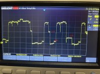
Point taken, although having just checked the same with my scope, I'm still seeing nothing at all.

UE13 & UE14 seem to be working but X8XX never activates. Does that lead us back to the ROMs again? (EDIT: I just put the PETTESTER in and now do get the CRTC CS flicker on reset. I'll have to look at this when I've more than a few mins to focus. I don't think it's as simple as bad sockets, but who knows)

Rust may never sleep, but again I need to. This day job is really getting in the way!
 
Last edited:
I brought myself back to the machine today for more probing.

With the NOP in place, I'm sure that addressing is all fine. I see the expected shapes and diminishing frequencies in various places, and CS's on all ROMs are good.

I decided to put Kernal and Edit back in (using fresh EPROMS and my 2332-2732 PCBs). Using a reset button, I noticed that between resets I get different types of CS activity each time. Sometimes it will be just US7. Often U6 and U7. If I try enough, I might get 4 of the ROMs with good CS.

There is activity on the data bus. I usually just accept that it looks like junk but took note of Hugos recent comment about needing to consider the levels. On all data lines there are levels such as 0.5v, 1.1V, 2.1V - given those are invalid TTL levels, is that just timing of inspecting a data bus or the sign of trouble we're looking for?


IMG_0228.jpg
 
The problem with looking at the data bus (without any other frame of reference) is that weird voltages can exist - providing that the bus is floating and not being used. If two (or more) things are concurrently driving the data bus during a READ cycle - this spells disaster.

When the data bus becomes tri-state (when nothing is driving it at - say - the end of a read cycle) the oscilloscope trace looks horrible!

Replacing the Kernal and EDIT ROMs on their own may not help. The OTHER ROMs are involved and can cause the machine to crash at random locations if they have bit rot.

The only way to get the machine to work is to install a known, good Kernal ROM and my PETTESTER ROM.

In this configuration, you should observe a very brief /CS activity on the Kernal ROM immediately after a reset and then constant /CS activity on the PETTESTER ROM thereafter.

If this does NOT work reliably, we need to investigate why and fix it first.

There is the possibility that another ROM (other than the Kernal and PETTESTER) is faulty and is corrupting the data bus without it being selected. This has been seen in the wild. If the other ROMs are in sockets, you need to remove them.

If you are not getting anywhere, you need to purchase a diagnostic unit that can be installed in the CPU socket and can map RAM and ROM between the PET and the diagnostic unit. These units usually contain a NOP generator and my PETTESTER.

Dave
 
With the EPROM Kernal & PETTESTER, it seems to run as you suggest although usually takes at least 1 reset.

If it's likely to help, I can remove the other 3 roms (they aren't socketed but that's OK). I've plenty of EPROMS and the PCB boards so can make up more adapters too.
 
No, please do not remove the other ROMs if they are not causing us problems.

Requiring a single reset implies that the 555 timer forming the reset is probably not working properly.

Connect a multimeter between 0V and pin 40 of the CPU (/RESET).

Leave the PET switched OFF for a while then power it on. How long (approximately) does pin 40 stay LOW for? Usually this is about half a second or more after the power has been applied.

With my PETTESTER in and running (constant activity on the /CS pin of the PETTESTER ROM and pin 7 of the CPU) what are you observing on the screen?

Dave
 
The 1 second sounds fine. This should reset the PET on a power up.

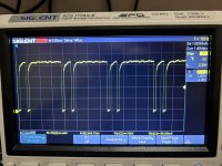
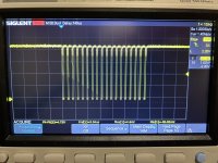
So, if the Kernal ROM is entering the PETTESTER ROM and the PETTESTER ROM has a constant stream of /CS signals you should observe some form of /CS signal on the CRTC (pin 25) when you reset the PET (or power it up).
Dave
 
On that issue of ambiguous logic levels on the data bus lines with the NOP running, I think I have seen this before in my 2001 PET , and it was working ok otherwise, so in this case with the NOP running I don't think that means a lot, however I could not spot this sort of thing with general operation of the computer though, so if it is seen then, it could indicate some conflict perhaps.
 
you should observe some form of /CS signal on the CRTC (pin 25) when you reset the PET (or power it up).

Yes, a burst of 36 (18x2 pattern)

When this repair went backwards, we were at the point that the pettester was displaying memory results, with the first byte good, then rest bad. I was probing DRAM signals when something seemed to fizzle. I recall at the time that the screen output remained on but the patterns of gbbbbbbbbbbbbbbbbbgbbbbbbbbbbbb etc had turned to junk. After reset, it was in the state it's in now.

IMG_0231.jpg

IMG_0232.jpg
 
Excellent, so we now know that the Kernel ROM is getting to the PETTESTER ROM and the PETTESTER ROM is initialising the CRTC.

As the CRTC sits on the CPUs data bus, and the PETTESTER ROM is also sitting on the CPUs data bus, I am quite confident that the data bus is OK.

Next...

Can you check for a 1 MHz clock on pin 21 of the CRTC and for activity on pins 22, 23 and 24 of the CRTC.

Is the CRTC in a socket?

Can you also check the power pins on the CRTC (pin 1 = 0V and pin 20 = +5V). Check both pins.

Can you then check the following pins of the CRTC for any sign of activity at all:

Pins 34 to 40.
Pins 4 to 13.
Pins 16-18.

I am off to bed now...

Let's just work the problem through.

Dave
 
Last edited:
Can you also check UD5 pin 8 for signs of activity?

This is the /CAS0 signal driving the low 16K bank of memory. If my PETTESTER is trying to test the memory, this signal should be active.

If there is nothing there, it may mean that the video RAM test has not passed. I would also check UE12 pin 9 (/SEL8 = video RAM).

Dave
 
check for a 1 MHz clock on pin 21 of the CRTC
1 mHz good (999.825)

activity on pins 22, 23 and 24
22: 170 kHz
23: 1 mHz
24: 298 kHz

Is the CRTC in a socket?
CRTC not in socket.

Can you also check the power pins on the CRTC (pin 1 = 0V and pin 20 = +5V). Check both pins.
1: 0.0319V
20: 5.1773V

Pins 34 to 40
34: low
35: low
36: low
37: low
38: 500 kHz
39: low
40: low

Pins 4 to 13.
All low

Pins 16-18.
All low
 
I am going to call the CRTC dead...

It is interesting that you have something on pin 38 though, but everything else being flatlined is not good.

As the CRTC data bus is directly connected to the CPU, I can't see any reason why the CRTC would not be programmed correctly...

Dave
 
Back
Top