• Please review our updated Terms and Rules here

A pair of Pets - Preparing to test after perhaps 40 years unused

I am going to call the CRTC dead...
If so, I'm not keen to butcher my other PET at this point - is Hitachi 6845 an OK replacement (I see that discussed in other threads where the original MC doesn't suit) or do I specifically need to source the MOS one?
 
You could try these ones:


Here is some info on 6545 and 6845 CRTC's:

 
Received my first delivery of replacement CRT's today, these are UM6845RA from a local enthusiast (the others that are due in a few days are the AliExpress gamble)

Removing the old IC, installing a socket and trying the new ones....unfortunately the exact same result including the signal on pin 38. Presumably my original isn't broken either, unless this isn't a suitable replacement.
 
Feeling a bit stuck and not wanting to endlessly hack up the board, what other diagnostic tools may help me?

Eg things like this?

 
There are a number of diagnostic boards available.

Their general operation is to replace the ROM and/or RAM of the PET. If the ROM or RAM is faulty, then this will cause the PET to operate. You can then fault find the offending sub-system.

Some of the boards have an inbuilt NOP generator, others not.

Some of the boards have inbuilt diagnostics of different types.

Bitfixer's and Nivag's boards contain my PETTESTER, the Tynemouth board doesn't.

They all rely on the video sub-system working however. If the CPU to CRTC interface doesn't work - you are stuffed...

We already suspect that my PETTESTER is working in your PET. I was surprised that replacing the CRTC did not work (in your case). Clearly, we have missed something somewhere.

Either the PETTESTER ROM (via the CPU) is not programming the CRTC correctly or the CRTC is not being fed with the correct hardware signals. As the CRTC is pretty much an autonomous chip (once programmed) it has to be down to the data bytes being sent to it or the hardware signals on the pins.

It will be just as demoralising to buy another board, pop it into the PET, and still get a picture of a "black cat in a coal cellar at midnight".

Do you have a logic analyser (I suspect not, but this is the best tool for diagnosing what is happening between the CPU and the CRTC in terms of its programming). Of course you do. I went back to read some of the previous posts!

Use the CRTC /CS (pin 25) as a trigger and monitor RS (pin 24) the data bus. If you only have 8 channels available, monitor half of the data bus with one trace and the other half of the data bus with a second trace. What we are looking for is what data bytes are written to the CRTC immediately following a physical reset - and to compare those with what are stored in the PETTESTER ROM.

Dave
 
Last edited:
The PETTESTER initialises the CRTC as follows:

18 registers are programmed - numbered from 0 to 17.

The register number is output to address $E880 first (CRTC /CS=low and RS=low).

The data for that register is then output to address $E881 (CRTC /CS=low and RS=high).

The data bytes programmed (from register 0 to register 17) are:

49, 40, 41, 15, 32, 3, 25, 29, 0, 9, 0, 0, 16, 0, 0, 0, 0, 0 (all in decimal). Sorry, you will have to convert them to hexadecimal yourself.

You should see the register number output to the CRTC first followed by the data byte for that register

The above configuration is for a PET/CBM 60 Hz (framerate) Business machine.

You can check (or change) what is in your particular ROM by reading it back and looking at byte offset 5 onwards for the 18 bytes of data that is used to initialise the CRTC. The bytes are ordered from register 0 to register 17. Check the data sheet(s) for the CRTC as to what these registers do.

Dave
 
Last edited:
Thank you, that's great to have the detail on how the CRTC initialises.

I've taken captures of the CS/RS and data - and had to do it in two goes as (and as you guessed) I've only got the small 8 channel analyser.

A 'good' screen shot is below but:
1) It took me multiple attempts to get what I'm showing below. I don't see these patterns at all on a hardware reset / power up. I have to trigger a soft reset to see this 18 pattern activity.
2) Even using the soft reset, I will often only get 18 single CS activations, aligning to "CS=LOW + RS HIGH". I have to soft reset a few times to see the double pattern shown below.
3) I decoded the bus across my two captures.....and it's just repeating FF, 17, FF, 17, FF, 17 .......

After the these captures, I took the PETTESTER and read it back. I can confirm that Byte 5 onwards is (hex) 31, 28 etc & it verifies correctly to the original PETTESTE2KV04.bin file.

I haven't modified the PETTESTER at all...you mention 60Hz values. Is the fact that my machine is a 80 column 50Hz an issue? We did pass the character test stage (originally slashes then occasional bad chars causing us to fix some logic and replace videm RAM) and had started troubleshooting DRAM tests earlier before something went bad.


8032-CRTC-DB-0-3.png
 
>>> Is the fact that my machine is a 80 column 50Hz an issue?

Nope... The only difference is the CRTC programming for the frame rate for the market that the machine was targeted for.

The fact that it worked BEFORE is a good indication that this is NOT the problem.

So, this tells us something that we didn't know before - and probably indicates why we (well I) got led up the garden path with the CRTC being faulty. If PETTESTER is running correctly (and it clearly isn't) then the CRTC should have been programmed correctly! It isn't... So, replacing a good CRTC with another good CRTC and programming it incorrectly should give us the same results (and it appear to do that very well!).

I am just thinking aloud here...

PETTESTER ***MUST*** be executing the code loop correctly in order to output the 18 double pulses. This implies that the Kernal ROM restart vector is being read correctly and is correctly entering the EDIT ROM (where PETTESTER resides). This implies that the CPU reading and executing instructions from ROM is fine. So we can't have a stuck data bit or anything obvious like that.

There must be an issue somewhere, however, if the wrong data is being read and/or outputted incorrectly to the CRTC (despite the fact that the EPROM is verifying correctly)...

It is also a little concerning that the power on reset and/or soft reset is not working every time. We did check that we were getting a good hardware reset on pin 40 of the CPU didn't we?

It is outputting to register 255 (FF) a value of $17 every time. I wonder if this corresponds to a specific value in the ROM code? I will check.

Let me have a think over lunch...

Just a thought. Have we tried a replacement 6502 CPU. This is a long shot - but it has been known for a CPU to fail...

Dave
 
This is the very tiny bit of code that is getting executed to initialise the CRTC:

Code:
E017                START:     
E017                             ; Initialise the CRTC (if it exists).
E017                             ; ===================================
E017   A2 00                  LDX   #0   ; Start with CRT Controller register 0.
E019                MORE_CRTC:    
E019   BD 05 E0               LDA   CRTC_INIT,x   ; Pick up the initialisation value for this register.
E01C   8E 80 E8               STX   crtca   ; Tell the CRT Controller which register we are going to initialise.
E01F   8D 81 E8               STA   crtcd   ; Initialisation value for the register just defined.
E022   E8                     INX      ; Index the next CRT Controller register.
E023   E0 12                  CPX   #12h   ; Have we finished initialising the CRT Controller?
E025   D0 F2                  BNE   more_crtc   ; If not, skip back and initialise more registers.

In order for us to only get one (1) CRTC /CS pulse of the pair (with RS=HIGH only) means that either the 8E instruction (STX) is not being fetched and/or executing correctly or the associated address (E880) is not being processed correctly. Or is the CRTC chip select logic not working correctly?

In order to get incorrect data, the LDA or STA instructions (or the associated data) must be misbehaving.

Again, just thinking aloud!

Dave
 
Last edited:
We did check that we were getting a good hardware reset on pin 40 of the CPU didn't we?
We did, and it was sufficiently delayed & reliable.

Have we tried a replacement 6502 CPU
I haven't tried a replacement, but I did put it in my VIC-20 a few days ago with the same suspicion. It worked fine there so presumably is fine unless the PET uses something the VIC doesn't. I do have a sealed & new W65C02 if there was cause to crack that out.

I've lots of uneducated thoughts but I'll keep them to myself and see what thoughts your lunch inspires instead.
 
If the 6502 CPU works OK in a VIC-20, that is good enough for me...

What Kernal ROM have you got in place? I know you have programmed it - but from which file?

Dave
 
What Kernal ROM have you got in place? I know you have programmed it - but from which file?
From Zimmers:

kernal-4.901465-22.bin

I just pulled that out too and verified it matches the download, it does.

It's on a 2732 using a 2332-2732 adapter I assembled from a PCB design I found / ordered on PCBWAY.
 
Last edited:
Ok,

You are not going to like the next bit, but you will learn a lot (if nothing else)!

I suspect our reset problem and the initialisation of the CRTC (or incorrect initialisation thereof) are related to the same issue. We have to assume that, or we will go mad! The simplest explanation is that there is one fault and it causes all of our observable effects...

A little explanation about the way a 6502 CPU performs a reset...

When pin 40 goes HIGH (and we know we have a good reset pulse on start-up), then the CPU should fetch two (2) bytes from addresses $FFFC and $FFFD in the Kernal ROM. These two bytes are loaded into the program counter and our execution should start at that point.

The byte at address $FFFC should be $16 and the byte at location $FFFD should be $FD.

The code that gets executed at $FD16 should be the following:

Code:
FD16: A2 ; LDX #$FF (The value $FF is in the next byte).
FD17: FF ; 
FD18: 78 ; SEI
FD19: 9A ; TXS
FD1A: D8 ; CLD
FD1B: 20 ; JSR $E000 (The address $E000 is in the next 2 bytes). This causes entry into the EDIT ROM = PETTESTER ROM.
FD1C: 00 ; 
FD1D: E0 ;

It should be possible to trigger your logic analyser on the Kernal ROM (UD6) /CS pin 20; and use the other channels of your logic analyser to look at the address pins of the Kernal ROM (and the data bus) to see what address is being fetched to start with (the first two address bus accesses should be from addresses $FFFC and $FFFD), and what data is fetched (it should be $16 followed by $FD).

This is the first thing we need to do to see if this address bus and data bus are consistently the same following a soft reset.

Are you happy with my explanation of how to continue?

Dave
 
OK, I think I understand the mission and suspect I’m really going to wish I had more channels. That might be for my 2024 Santa stocking.

In the meantime, I’m going to be out of town for a few days so likely won’t be able to get back to this until next weekend.

One thing I know as I pack up for this weekend is that on initial power up, the EDIT ROM never gets it’s CS activated, but soft reset will kick it in.
 
No problem.

I am away sporadically for the next 3 weeks with work - but I will have my phone with me to continue to point you in the direction of a rabbit holes :)!

>>> I’m really going to wish I had more channels.

Yes, that's what I was thinking also...

>>> One thing I know as I pack up for this weekend is that on initial power up, the EDIT ROM never gets it’s CS activated, but soft reset will kick it in.

That is what I remember you saying - which is weird (unless the LOW to HIGH edge of the reset signal is in some way being 'lethargic'). The two situations (power-up reset and soft reset) should (logically) be the same. The only difference is that the +5V power rail will not be coming up at the same time. Neither will the crystal oscillator. Two things do now jump to mind: (1) is the +5V rail getting to > 4.75V DC before the /RESET signal performs its LOW to HIGH transition and (2) is the CPU clock starting up BEFORE the LOW to HIGH transition of the /RESET signal? Read up on what happens during a 6502 reset (read here: https://eater.net/datasheets/w65c02s.pdf).

Dave
 
Back home, answering the easier part first. The deep breath and trying to tie together the address lines will be for my Saturday.

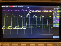
Purple = 5V
Yellow = Reset 6502 P40
Green = PHI2 6502 P37

This seems to be OK right? Or are the clock pulses too low?

IMG_0293.jpg
 
The timing looks fine.

The +5V is there - and the clock has clearly started up BEFORE the /RESET signal has gone away - so all that looks good.

Not sure about the voltage levels though? What is the -2.XX indicating?

I am expecting voltage levels between 0V and +5V of course (o.k. the clock signal may be a bit different in terms of the voltage levels).

We have the hottest day of the year here so far - but I assume this is just 'normal' to you guys down there!

Dave
 
The -2.x V is just vertical offset as I scrolled them all down a bit so I could keep 1V scale on the grid. They aren’t all lined up either so we could see them.

The voltage and reset are getting to 5.1 - the clock is less than 4V and that weird shape at the top fluctuates fairly randomly. Could that point to issue on clock circuit?

Colder than usual here…
 
I wouldn't worry too much about the clock - that looks fine to me (considering the circuitry used to generate the clock!).

The levels are fine for a TTL signal...

I am sure our temperature will be back to normal shortly!

Dave
 
Back
Top