• Please review our updated Terms and Rules here

AIM-65 Tape Adapter.

Hugo Holden

Veteran Member
Joined
Dec 23, 2015
Messages
4,808
Location
Australia
I had never used my AIM-65 with tape storage, so I thought I would have a go connecting to a Tape Deck.

All did not go as smoothly as planned.

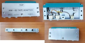
Firstly I didn't like the idea shown in the manual on connecting the lead wires to an Edge connector. I figured it would be a lot better to combine the edge connector with a metal shell and fit 2.5mm & 3.5mm panel sockets to it, this way standard link audio cables can be used, much like they did on the SOL-20, they had these connectors on the SOL's mobo. So it took me a while to construct that.

After that, the problems began.

I did not have any known good recordings on hand and I was not sure if it was a record or playback issue.

I could record a file to tape and play the tape back, it looked like reasonable looking data on the scope. However, the recording was not recognized on a load and the computer would just hung waiting for the file. I confirmed the playback signal was reaching the 6522 VIA ok.

I examined both the output signal on pin 8 of Z5 and the recovered playback signal on pin 7 of Z 8, the zero crossing detector, and the data looked respectable on playback, but after a while I noticed an odd peculiarity; the data output for recording, measured on the output of the gate Z5 pin 8, had regular lower frequency breaks in it, but oddly, the recovered audio on playback didn't.

Just as I was pondering why, I noticed that one leg of the audio output coupling capacitor C5 was broken off. Yet, despite that, where you might think the tape recording would be totally zero, the tape deck's sensitive mic input was picking up enough signal by stray coupling, to make a form of a recording, even from the low level output I had selected. But, the signal was so heavily differentiated, basically just recording high frequency transients, it was corrupted and a bad recording was made. Now fixed.
 

Attachments

  • AIMADAPTER.jpg
    AIMADAPTER.jpg
    260.8 KB · Views: 13
I have been optimizing the tape interface with the AIM, part of it relates to my tape decks, but I have some measurements that could be useful to others.

I was reading that somebody thought that the input comparator (used a as zero crossing detector) on the audio input in the AIM did not have enough hysteresis, and when its was set near zero crossing there were oscillations on its output, I checked that, it was true there was a 5MHz oscillation there with the original factory setting of VR1 which was set for zero crossing detection.

They recommended lowering the 5.1 meg hysteresis (Positive feedback) resistor to around 500k, so I did that, it helps the noise immunity a little too. Though in this application the signal levels are well above the noise.

I set up the comparator's bias control VR1 in the AIM according to the SYN-recording & playback method in the manual. (Shades of the "Syncording" in the Movie the 6th Day). The idea being that VR1's setting is optimized for the lowest possible level signal from the tape deck to reliably acquire the data. Other methods to set VRI include simply doing it with no signal input, so the comparator output in just on the verge of changing state, in other words a zero crossing detector.

Using the SYN-cording method, and setting the comparator's preset VR1 to the most discriminating position with the volume on the Tape Deck turned to the lowest possible position, the signal at the audio input to the AIM just failed to read at a level of 300mV peak to peak (that is with the lower value hysteresis resistor). The recorder I have at full volume output, puts out a clipped looking square wave of about 9V peak to peak, and under 8V its not clipped, and the waveforms appears more sinusoidal.

So the input on the AIM can accept a wide range of levels >300mV pp to 9Vpp, clipped or not, without a problem.

After VR1 was set, I found the comparator output sitting high with no oscillations with no input signal, but it will be very close to changing state. To give it some margin though, ideally the input signal (output from the tape deck) would be greater than 1 volts pp at least. 1N4148 diodes at the comparator's input clip it off to +/- 700mV there, but due to the input resistor network, the voltage has to be higher than this to get the diodes to conduct .

I looked at the high and low output signal levels that the AIM sends to the tape deck for recording. The low level output is close to 40mV pp. This suits the mic input on most decks. Certainly that record level is enough on playback, at full volume, in my tape decks, to drive their audio output stage into clipping.

The high level audio out from the AIM would better suit a line input on a tape deck and it is around 1.8v pp.

The audio input signal processing circuit, shown on page 8 of this article I wrote about the SOL-20 is somewhat more elaborate than the AIM-65, including an advanced tone decoder & recover clock circuit, a PLL and a lot more processing prior to the UART:

www.worldphaco.com/uploads/The_SOL-20_tape.pdf

The SOL used the Kansas City format at 300 Baud and a 1200 Baud option they had with CUTS. I wrote a lot about it in the article.

I have not investigated the AIM-65's signal format yet, I know it can also be configured to accept KIM-1 recordings, with a change in a memory location. They have certainly significantly simplified the interface compared to the SOL and sending the signal directly to the VIA.
 
Last edited:
Another thing that happened, during my recent adventures with tape decks and the AIM:

The two Tape decks I'm using are both vintage Panasonic Slimline types. They were new old stock. It has been a while since I used them with the SOL. Both had exactly the same issue, while Play & Record worked, both fast forward and rewind didn't with very weak force on the tape hubs and a slipping sound. I did the usual things cleaned the idler wheel rubber, drive belt, clutches etc no help.

I had to pull the whole mechanism apart.

It turned out that a small plastic intermediate gear wheel involved in transferring the forces for REW and FF had microscopically shrunk and become very light on its shaft. The shaft was in good order polished and exactly 2mm diameter on the micrometer. But, the hole in the gear wheel was now just fractionally under 2mm, making it a very tight fit on the shaft.

Being a Nylon like part , I couldn't machine that easily to enlarge it, so I simply stretched it by passing a 2.1mm shaft through the hole. The wheel then ran freely, problem solved. Both the tape decks were identical with this problem. Peculiarly, the type of Nylon like material this particular gear wheel was made of, is semi-transparent, unlike the opaque white Nylon gears in the rest of the mechanism. Whatever material it is, it shrinks over time. If initially the clearance was say 0.01 to 0.02 mm, probably to get it tight it would have to shrink by about 0.02mm to 0.04mm at least, or say about 1% maybe 2% to jam it on the shaft. So in terms of material shrinkage, doesn't seem like much. Of course if it had expanded by a few %, rather than shrunk, there would have been no observed problem.
 
Last edited:
Back
Top