• Please review our updated Terms and Rules here

AIM-65 Video Output Success.

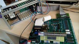
I did notice an interesting effect, when the CRTC card and the AH5050 Flier were running together. When the Filer was started with the F1 key, the string of characters displayed were being weirdly modulated with some rectangles, like a miniature 4 block checkerboard, that was changing with time. Maybe that was the periodic interrupt where it was interfering with the AH5050 activities.

If the interrupt routine is saving and restoring the processor state, then the CRTC should be none the wiser, as the CRTC chip handles all the timing transparently to the CPU.

Is it possible that with the AH5050 and CRTC installed, some of the AH5050 is being intercepted by the CRTC and causing odd effects such as placing it it graphics mode? Would it be possible to have the "F!" code restore the I/O vectors to bypass the CRTC for the save/load, and then have an "F2" to re-initialze the CRTC afterwards? Even better, is it possible to intercept the SAVE/LOAD commands and add that little bit of configuration so it happens automatically? I'm at work so I am unable to reference the manuals at the moment.
 
The SAVE and LOAD commands go via the wedge that we install. That was painful enough for the AH5050 (having to reverse engineer it). It is what I am thinking of - if we can reassemble the AH5050 firmware (we have a pretty good disassembly) for a different address - and modify the interrupt behaviour - this may kill two birds with one stone (so to speak). Relocating the AH5050 will mean that the assembler ROM can stay where it is - and disabling/enabling the interrupts at the appropriate points will (hopefully) make the two ROMs coexist with each other.

This will be a pain to do though - so we would need some evidence whether this is the root cause before embarking on another journey to Mordor!

Dave
 
Daver2 Dave, two questions about your idea;

If the AH5050 ROM was moved to another address, where should it be moved to ? I was looking that the AIM-65 memory map and I couldn't see an obvious place to put it because existing ROMs Z22 to Z26 occupy all the space from $B000 to $FFFF and the RAM occupies lower memory and there is the user area in between, would it go in the user area ?

How can we confirm, with an experiment, if interrupts are involved in the conflict (eg check the activity on NMI, & IRQ with the scope) or if the conflict is simply coming about because the two programs using the same memory locations for data ?

I am working on a solution, a variation on the hardware control of the RM-65 CRTC, will report results today.
 
Ok, I think the problem might be solved.

While tinkering around with the hardware I noticed that when the display control is returned to the AIM-65 LED display, after using the CRTC, by issuing the CTRL-Y command to the CRTC card, the CRTC card itself appeared to become inactive and for example not respond to any more control commands and its video output not change.

This got me wondering how in that condition it could interfere with the Filer at all , so I tried again, after creating a BASIC program with the CRTC running, going back to the AIM-65 display with CTRL-Y and attempting to use the BASIC SAVE and LOAD functions (after re-initializing the Filer) and it now appears to work, the Filer functions normally and the CRTC card does not appear to be interfering with it at all. Why it seemed to before, I'm not sure. Perhaps I was doing something wrong in the sequence.

One thing though, if a saved File is loaded to BASIC from disk, it is required that the CRTC card, to take over the display again second time around, is warm started not cold started.

This is done as explained to me by dfnr2 Dave:

<M>=010C
</> 010C 4C C0 0F ; set the F1 vector. Note the little-endian byte order
<M>=0FC0
</>=0FC0 20 64 99 60 ; code snippet for JRS 9964; RTS​


I will keep working on it, trying everything multiple times, and write out the orderly sequence of instructions, if they consistently work.
 
I have drawn up the sequence of instructions that gets around the conflict, attached as a .pdf. I will add these to the article about the RM-65 CRTC card.

dfnr2 Dave, can you try this too on your system ? it works on mine.
 

Attachments

  • CRTCAH5050.pdf
    169.3 KB · Views: 10
I would love to try it, but don't have the AH5050 setup. I do have a 1541 drive, but lack the interface.

I was planning on making an AH5050 interface, but now I see that someone already has created a board:

https://www.vcfed.org/forum/forum/ge...06#post1206706

Dave

That's right, I forgot that you did not have the AH5050 / 1541 Drive system running yet.

I have tried the protocol I posted in the .pdf many times now and it is working fine every time I try it, avoiding the conflict with the CRTC card and the AH5050 system.

I have just about finished the article on this RM-65 CRTC card, I should be able to post a link to it tomorrow.

It is good that somebody else made an AH5050 compatible system at least, because I promised the fellow who sold me my AH5050 pcb, on his request, that I would never reproduce it and sell it, so it would not have been possible (ethical) for me to able to supply or reproduce the pcb.
 
Last edited:
That's right, I forgot that you did not have the AH5050 / 1541 Drive system running yet.

I have tried the protocol I posted in the .pdf many times now and it is working fine every time I try it, avoiding the conflict with the CRTC card and the AH5050 system.

I have just about finished the article on this RM-65 CRTC card, I should be able to post a link to it tomorrow.

It is good that somebody else made an AH5050 compatible system at least, because I promised the fellow who sold me my AH5050 pcb, on his request, that I would never reproduce it and sell it, so it would not have been possible (ethical) for me to able to supply or reproduce the pcb.

Of course, one might consider the RM-65 floppy controller board that was intended to be used with the RM-65 family of parts. There were a few compatible Disk operating systems that were used. The other is the FDC-1 ( name used for several disk controllers ). It was made to be compatible with the KIM/SYM/AIM65 edge connector. I have one of those that I'd intended to get working on with a SYM-1 and a KTM keyboard/Display board. When I finally retire, it is on my list of projects to finish.
Dwight

Dwight,

The thing is, with most RM-65 cards, they appear very difficult to get. It seems very few people who have them want to sell them.

It would have been cheaper and easier for me to have bought a CRTC card for $1000 or more on ebay (if there was one actually there) than to have done the pcb replication. But, not being able to get the CRTC card (and wanting one badly) forced the replication.

It is just like those Dazzler pcb sets, they come up for sale very infrequently and when they do cost a small fortune.

Although I saw an "ACIA" RM-65 pcb on ebay a while back. But I don't know how easy the RM-65 floppy controller pcb would be to get. Probably though, the level of difficulty associated with its replication, would be similar to the CRTC card, which so far has been the most difficult pcb replication project I have yet tackled.

There was a fellow in the USA who had a large collection of RM-65 cards, these were sold off to a collector in France as one lot and disappeared into thin air so to speak.
 
I'll have to admit, I've not seem many come up on ebay. I do have a frame with 32K of RAM, floppy controller, serial card and cpu card. The original code on the serial card expected to initialize the CRTC card but it didn't come with my frame. I've made a patch to use the serial but haven't had time to fiddle with it. It has a secondary bus with 8K of RAM that has a cross over board that looks to be some type of IC board but it didn't come with the IC cpu card. I plan on getting it up and running with a disk drive I got for it.
Right now I'm busy with some I4004 stuff I'm expecting to show at the West Coast VCF, coming up in August.
Dwight
 
Here is the provisional article about this project:

https://www.worldphaco.com/uploads/THE RM65 CRTC MODULE AND THE AIM.pdf

I hope the link works, I have had a lot of trouble with my website recently. I set it up to be a repository for .pdf files, nothing more elaborate, sounds simple right ? If only software was as simple as the solder, copper tracks and digital microcircuits. It is a good thing that pcb tracks don't "update" themselves in the middle of the night.
 
Hugo,

The link worked for me OK.

I will have a read when I get a bit of free time (or get bored with reviewing documents at work)...

>>> It is a good thing that pcb tracks don't "update" themselves in the middle of the night.

Tin whiskers :)...

Dave
 
Dave, good point !

Excluding my comms radios that died with AF11X series Whisker affected transistors, I have had two separate "Tin Whisker events" in my workshop.

One was in a LG computer VGA VDU, the fault appeared as the screen menu spontaneously appearing as though a Ghost had pushed the menu button and at exactly the same time the screen contrast changed on exactly 1/2 of the image, split down the middle. The trick was realizing that two entirely different parts of the circuit were affected simultaneously (linked by a whisker) .It was a whisker on the finely spaced pins of the LG Flatron processor IC, also the board boasted "Lead Free" on its markings. At least that was a fairly easy fix. There were, under magnification, multiple whiskers but most had not shorted pins together yet, it just takes one to produce a fault.

The other one was a "Nightmare" and used up a week of my time (because with a hardware fault I never give up). It was a random downward deflection of the CRT beam in one of my beloved 2465B scopes. The Tin whisker causing the trouble was on the underside of the main board which required removal (big job). Later I found out that a service center in the USA had abandoned a number of 2465B main boards due to failure of unknown origin, they had not figured out it was the whiskers. They occur at a certain point on the pcb where there is no conformal coating. I wrote up an article on the problem to help others with 2465B scopes:

https://www.worldphaco.com/uploads/T...K_LEAKAGE..pdf

Needless to say, after that, I'm a big fan of Lead based solder and stick to Ersin Multicore and when I think of "Lead free solder" it sends shivers up my spine. Its a good thing they never fell for it for Mil spec and Avionics applications, otherwise I would never get on a plane again.
 
Last edited:
I would love to try it, but don't have the AH5050 setup. I do have a 1541 drive, but lack the interface.

I was planning on making an AH5050 interface, but now I see that someone already has created a board:

https://www.vcfed.org/forum/forum/ge...06#post1206706

Dave
Aside from the connectors it consists of nothing more than a 7406 and three pull-up resistors; as a matter of fact the same circuit is used to connect a Commodore PET to a 1541 or compatible.

Great piece of work there, Hugo; congratulations. I haven't been on here for a while and wondered how you made out with that project; glad you got the conflict sorted out.

m
 
Hi Hugo,

I made the layout for the RM65 CRTC based on your PDF template. The boards were made at Allpcb.com. I also quickly made a backplane. If small errors are corrected, I can provide the Gerber files if you are interested.

Thank you for making and sharing the template. The CRTC runs very well. And people who have been looking to own a CRTC for a long time can build one cheaply.

Best regards,
Jörg
 

Attachments

  • AIM_RM65.jpg
    AIM_RM65.jpg
    815.7 KB · Views: 20
  • BP.jpg
    BP.jpg
    1 MB · Views: 18
  • PCB1.jpg
    PCB1.jpg
    893 KB · Views: 20
  • PCB2.jpg
    PCB2.jpg
    788.1 KB · Views: 19
Here is the provisional article about this project:

https://www.worldphaco.com/uploads/THE RM65 CRTC MODULE AND THE AIM.pdf

I hope the link works, I have had a lot of trouble with my website recently. I set it up to be a repository for .pdf files, nothing more elaborate, sounds simple right ? If only software was as simple as the solder, copper tracks and digital microcircuits. It is a good thing that pcb tracks don't "update" themselves in the middle of the night.

I just visited the site, at the bottom of the homepage there's a link to "Uploads", but clicking it gives a 403 error.
 
I have the PDF in four sections.

Best regards,
Jörg
 

Attachments

  • 1-6 -THE RM65 CRTC MODULE AND THE AIM.pdf
    1.2 MB · Views: 14
  • 7-8 - THE RM65 CRTC MODULE AND THE AIM.pdf
    799.1 KB · Views: 12
  • 9-14 - THE RM65 CRTC MODULE AND THE AIM.pdf
    1.7 MB · Views: 10
  • 15-23 - THE RM65 CRTC MODULE AND THE AIM.pdf
    608.8 KB · Views: 11
Hi Hugo,

I made the layout for the RM65 CRTC based on your PDF template. The boards were made at Allpcb.com. I also quickly made a backplane. If small errors are corrected, I can provide the Gerber files if you are interested.

Thank you for making and sharing the template. The CRTC runs very well. And people who have been looking to own a CRTC for a long time can build one cheaply.

Best regards,
Jörg
Hi Jorg,

Nice Job !

Can you send me your Gerbers for the CRTC board, to Hugo.Holden9@gmail.com

As I noted my pcb maker made two track errors on the gerbers, so it would be good to have accurate ones.

Best regards,
Hugo.
 
Hi Hugo,
as soon as I have revised the layout, I will send it to you.
I'm currently finishing another layout. I guess you'll have it this weekend.

Best regards,
Jörg
 
@Hugo Holden and @yogi63 I'm about to join the clu on the AIM-65 and I'd like to build myself a video board. Has there been any further development on this project over the last couple of years? Jörg are your gerbers still available? I'll probably layout my own board, but having a working example to start with could be useful.

Also, any better copies of the schematic than the rough PDF on the first page of this thread? It's not the easiest thing to read, though most of it is self explanatory.

Scott
 
Back
Top