| VCF West | Aug 01 - 02 2025, | CHM, Mountain View, CA |
| VCF Midwest | Sep 13 - 14 2025, | Schaumburg, IL |
| VCF Montreal | Jan 24 - 25, 2026, | RMC Saint Jean, Montreal, Canada |
| VCF SoCal | Feb 14 - 15, 2026, | Hotel Fera, Orange CA |
| VCF Southwest | May 29 - 31, 2026, | Westin Dallas Fort Worth Airport |
| VCF Southeast | June, 2026 | Atlanta, GA |
-
Please review our updated Terms and Rules here
You are using an out of date browser. It may not display this or other websites correctly.
You should upgrade or use an alternative browser.
You should upgrade or use an alternative browser.
Atari ST on Amiga 1080 monitor?
- Thread starter Divarin
- Start date
Divarin
Veteran Member
True, but if I messed up making this cable I'll probably mess up making the Amiga's cable as wellThe 1080 should work. Even if vhold was out of wack on it you would at least see a rolling picture of some kind.
I’d try another source just to rule out issues with the monitor. If you get a picture with your amiga then you’ll at least know it’s your cable that’s the culprit
")
Divarin
Veteran Member
That would be helpful, thanks! I'll see about getting some composite sync out of my ST.Ooo looks like you may want to try that composite video circuit after allI have a 1080 to amiga monitor cable lying around here somewhere I can tone it out and see if it is in fact using composite sync
Divarin
Veteran Member
Ah! so that's the problem then. I had it right the first time, trying to use only composite sync. Except that a) I don't have a composite sync and b) my wiring diagram was backwards.So I just checked my commodore branded cable for the amiga to my 1080 and there is only csync. Pins 8 and 9 on the 9 pin din are not connected
Okay, guess I'll hunt around and see if I have the components to build that composite circuit. Looks like it's unpopulated on my ST and most likely is on my friend's as well.

Divarin
Veteran Member
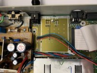
hmm I'm looking at those unpopulated pads: R51, R50, Q8, R49, CR11, CR10 but those markings aren't consistent with the schematic, they should be: R125, R126, Q12, R127, CR12, CR13
Maybe just that the schematic is from a different model?
Maybe just that the schematic is from a different model?
What revision board do you have? It’s also very coincidental that the silkscreen is showing 2 diodes, 3 resistors and a transistor and those are exactly what is required for that circuit haha. I tend to gamble though but I think it’s probably a safe bet
Check out page 2 of that forum post I originally posted looks like someone had same board (or at least that same portion of the modulator) and populated with success.

 forums.atariage.com
Found a working SCART->HDMI adapter on Amazon
Attachments
Divarin
Veteran Member
Looks like Rev. CWhat revision board do you have? It’s also very coincidental that the silkscreen is showing 2 diodes, 3 resistors and a transistor and those are exactly what is required for that circuit haha. I tend to gamble though but I think it’s probably a safe bet
damn no matter how many spare parts I horde I never have the right ones. I miss radio shack. Or a substitute for that transistor. I do have 2n2222's, which ... I'd have to put it in backwards and the voltage would be off a bit so... nah. I may have to order parts :/
SiriusHardware
Veteran Member
In case it's not clear from the photo the allocations of those values for the resistors are
R49 = 10K
R50 = 100R
R51 = 150R
R49 = 10K
R50 = 100R
R51 = 150R
Divarin
Veteran Member
Alright got the components and it's working!
Only strange thing is R51, for whatever reason, one of the holes isn't a hole, it's just a pad, it doesn't go all the way through. For now I just kind of surface mounted the leg on that side but I found where it connects to that pin header row (unpopulated) so if it breaks loose I'll run a wire to there.
The monitor is kind of soft though I may open it up and see if there's any internal adjustment pots I can try, like a focus.
SiriusHardware
Veteran Member
One end of R51 goes to the vast surrounding ground plane area which will suck up 90% of any heat applied to the pad - there very likely is a hole there but it would take an enormous amount of heat to melt the solder which is blocking the hole. If you seriously want to try you'll need to bake the surrounding ground plane area up to a pretty high temperature with a hot air wand before attempting to clear the hole with an electrical pump assisted desoldering iron.
Or, you could just leave it soldered to the surface
Nothing will disturb it once the machine is back together.
Or, you could just leave it soldered to the surface
Nothing will disturb it once the machine is back together.
g4ugm
Veteran Member
Looking at the circuit of the 1080 I wonder if that also has missing components as its supposed to accept H & V sync. Mind the Atari is probably easier to fix.
Great to hear you got it working!!Alright got the components and it's working!
Only strange thing is R51, for whatever reason, one of the holes isn't a hole, it's just a pad, it doesn't go all the way through. For now I just kind of surface mounted the leg on that side but I found where it connects to that pin header row (unpopulated) so if it breaks loose I'll run a wire to there.
The monitor is kind of soft though I may open it up and see if there's any internal adjustment pots I can try, like a focus.
Divarin
Veteran Member
yeah, thanks for the help everyone! the focus was easy to adjust, it's looking pretty sharp now. my friend will be stoked to finally be able to use his ST.Great to hear you got it working!!
Divarin
Veteran Member
I sold the monitor on to my friend and all's good there but now I'm looking at my ST setup.
What I've been doing is running it through a ST -> VGA cable I made and into an LCD monitor which supports the sync frequency of the ST. It's always been a bit dark and also the picture is shifted to the left side of the screen.
Now that I've modded my ST to have composite output I was thinking I could make a cable to connect it to my Commodore 1702's composite input jack. So I made that cable but the picture is black. If I turn the brightness way up and look real close I can see the outlines of the icons on the TOS desktop so I'm wondering if maybe the part of the composite circuit I ended up making by adding those few components was just the sync without the actual video or ... something?
I know composite *should* look less good than RGB (VGA) but given the poor picture quality I'm getting on my LCD monitor I thought composite might actually look better, if I could get it working.
SiriusHardware
Veteran Member
Um. As you already suspect, you modified your ST to produce composite SYNC, not composite VIDEO.
Only STs with modulators include the circuitry to combine the R,G, B and sync signals in a composite VIDEO signal which is then sent to the monitor socket and the RF modulator.
Even if you found a modulator to fit into the unpopulated modulator outline on your PCB that wouldn't 'just work', as it would also require a colour carrier signal input from a whole other circuit section which won't be present on your PCB.
I'm afraid you will have to use RGB + sync or nothing. Don't I remember you having a suitable monitor which you managed to get going with your Spectrum +2?
Divarin
Veteran Member
Yup that's was me. It is mostly suitable but it doesn't look great. If I crank up the brightness it's not too bad but I've been looking for ways to get a clearer, better picture from it.
As for the Spectrum +2 it's kind of the same cable in a way. So what I did was, since I already had the ST cable going into the VGA on the monitor, and I didn't feel like constantly getting behind the monitor to swap between ST & Spectrum, I made my Spectrum cable to plug into the 13-pin din of the ST cable.
Interestingly the Spectrum's picture (routed through the same cable) is bright, crisp, and clear (and properly centered).
I may just have to hold out for a 1080 monitor of my own (or something similar).