• Please review our updated Terms and Rules here

Attaching a battery to a 386 motherboard

boggit

Experienced Member
Joined
Jan 4, 2024
Messages
180
I'm shopping around for 386 motherboards and stumbled upon one such item, available from a domestic vendor via a Swedish online auction site.

The price is not unreasonable, but it seems to lack a battery, as per the picture below:

555482581_30346540-6c0b-4c1e-8a66-1a559d802895.jpg


Question: Is there any way of attaching a battery to this motherboard without soldering?

I have no soldering equipment, no experience with soldering and no space in my small two-room apartment to solder.
 
See the "EXT BATT" (J4) pins above the AMI BIOS chip? Determine the voltage and pin out and just plug it in.
 
Ah, most excellent! I somehow misread J4 as "EXT. BPT".

What sort of device do I use to plug the batteries in? I assume the pins are for some sort of battery holder?
 
I generally use an AA battery holder, You can get them with wires attached, You need to know the voltage requirements and pinout, see if you can find a manual for that board.
 
I generally use an AA battery holder, You can get them with wires attached
Excellent!

You need to know the voltage requirements and pinout, see if you can find a manual for that board.
Seems to be easier said than done. I haven't had much luck so far, but I will continue the search.
 
Looking at the motherboard photo, the 'external' battery would be attached, polarity wise, per below:

1709326825303.png

I can tell, because the pin that I have marked as positive goes to the positive leg of capacitor C8 and the anode of diode D1.

Diode D1, which in series with the 'external' battery, will reduce the voltage that reaches the HM6818 chip, and so a 3V coin cell (when new, measuring perhaps 3.3V) will be borderline for the HM6818 chip.
 
Looking at the motherboard photo, the 'external' battery would be attached, polarity wise, per below:

View attachment 1274688

I can tell, because the pin that I have marked as positive goes to the positive leg of capacitor C8 and the anode of diode D1.

Diode D1, which in series with the 'external' battery, will reduce the voltage that reaches the HM6818 chip, and so a 3V coin cell (when new, measuring perhaps 3.3V) will be borderline for the HM6818 chip.

Thank you! Good to know!
 
And the information at [here] might somehow assist you.

( Note that the IBM 5170 motherboard has two diodes in series with the battery, which results in a 3V battery being unsuitable for the 5170. )
 
And the information at [here] might somehow assist you.

( Note that the IBM 5170 motherboard has two diodes in series with the battery, which results in a 3V battery being unsuitable for the 5170. )
Great!

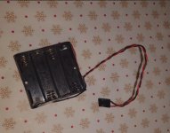
The vendor agreed to include this in the sale (4.5v):

IMG_8414.jpeg

Should do the trick!

Not really sure though where/how to place the holder. Perhaps taping it to the nearby PSU using a healthy ammount of electrical tape?
 
You can short such a battery rack to provide 3 or 4.5V instead of 6 and I think it's already connected to provide 4.5V judging where black wire is.
 
Yeah, I asked the vendor if it was 6v (figuring 1.5+1.5+1.5+15=6) but he specifically stated that it is 4.5.
 
Yeah looks like it's been 'modified' to just take 3 x 1.5v AA cells = 4.5v

Not really sure though where/how to place the holder. Perhaps taping it to the nearby PSU using a healthy ammount of electrical tape?
Velcro / Double sided tape ??, Keep the battery pack away from the motherboard, Those AA cells can leak, Maybe put the battery pack in a plastic bag just in case.
 
6V is well within the ratings of an MC146818, when dropped with two diode drops. When Taiwanese tower kits were shipped, they always came with 4xAA cell holder--I have a couple of systems so wired and they're still working after 30+ years. No matter your battery choice, do yourself a favor and place it in a plastic bag, so if it does leak, the damage will be confined to the holder.
 
Back
Top