• Please review our updated Terms and Rules here

AY-3-8500-1, PONG chip question.

syzygy

Experienced Member
Joined
Apr 22, 2023
Messages
401
Location
North East USA
I was doing some crate digging on the bay. I ended up buying these five chips for ~$15 (including the $5 shipping). The GI AY-3-8500-1 is what caught my eye. Check out the data sheet. It is a PONG chip (and the NTSC one). I want to see it play again.
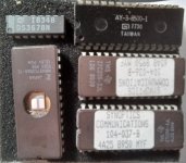
baychips 20230929_185802.jpg

There are a few articles around that use it, but I was taken by the project article by Steve Ciarcia in the Oct, 76 issue of 73 (p.104) https://archive.org/details/73-magazine-1976-10 Along with Don Lancaster, Steve Ciarcia taught me more about computer electronics than anyone – and I never met either one. While some would argue that I don’t really know much (hey, I try), those guys were really impressive and for many years.

What’s my question…., hang on, it’s coming. The few times I purchase such “untested” stuff on the bay, I think “untested” is a synonym for “bricked” or “fried”. Thus, my immediate goal is to do the bare minimum with what I have to test if the chip is functional. I figure, I need a clock and with that and maybe a few other passive components, I should see if I am getting any video out signals.

So, I start to make a clock, just like in the article, and I have only a few inductors and I can’t hit the 90 uH. The closest I come is an oscillator with ~1.74 MHz out – short of the 2.0 MHz required in the data sheet. My thinking is that if there is enough evidence that it is working than I will buy the proper inductor or a crystal.
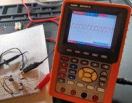
AY clock 20230929_185902.jpg

My question – do you think that clock speed I have is enough to test the chip at all – not expecting a visible video signal, but something to merit further work?
 
It won't sync on a real TV at the wrong rate, but it's close enough to look for waveforms on the individual outputs. At the very least you should see the 15KHz/60Hz sync on pin 16.

EDIT: also if you have a 4MHz or 8MHz crystal you can simply divide it down through a couple of flip-flops
 
Last edited:
Yes, as long as there is some sort of clock present it should do 'it's stuff' but at a proportionally lower speed.

Dave
 
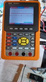
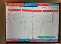
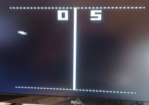
@Bruce Tomlin @daver2 Thanks for the help. I hooked it up with the clock that I had and I get a reasonable output on pin 16 (sync).

AY3 sync 20231001_095631.jpg

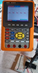
It also looks like I am getting an audio signal on pin 3 (I have the game set on practice),

AY-3 audio 20231001_100008.jpg

There is enough to continue. I will probably just get a 2.0 MHz crystal and with a 4001 and a couple of caps, that will be it. I can only find one place for a suitable adjustable inductor and almost no place for a 90 uH fixed inductor. . I have other stuff to get at Mouser, so I might as well pay one shipping charge.
 
Last edited:
My favourite Pong chip will still always be the MOS 7600/7601.

In my background reading for the GI chip, I have learned much about the Pong times - some of which I probably forgot, but much of which I never knew.
This is a nice site for the Pong Story. They mention the mostek chips and so many others that I did not know about. I even found a link to the GI databook that has other video game chips.

I will always have a soft spot for General Instrument ICs because a few were available at Radio Shack and that allowed me an introduction and easy access to some sound/music and speech chips.

At the time these pong games were commonplace, the home computer was becoming popular and the inevitable market crunch must have been predictable.
 
Last edited:
LOTS of history in that volume - tks
Great book! I have that one along with the (sort of) companion TAB book about repairing video games which I believe even has the schematic for game circuit that uses the above mentioned pong chip. It's a shame that so many of those old books aren't in print and the og copies often have big price tags put on them. So much amazing information in their pages. Sorry, I get all excited when one of my favorite books get mentioned, lol....
 
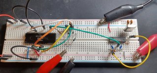
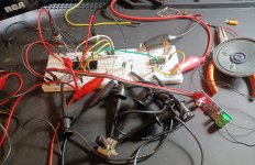
Still moving forward.

AY continues 20231013_090842.jpg

I have tested out pretty much everything and it all works. It is actually a pretty straightforward and simple chip.

Audio works fine run directly into the RCA TV component in for audio. It also works as input into a 386 amp and local speaker.

Ball angles/speed work. Bat size works. BTW, small bats at fast speed is very hard.

Manual/automatic serve works.

I thought about it a lot and I don't think I will do the rifle (the photo transistor gun). My recollection was that these never worked well.

One problem I had for a while is that the chip would not power up well - showed a mixed game screen and had an annoying and continuous sound until I pressed reset. I have been using several different schematics - for example, you can use a 4072 or straight diodes to combine video outputs.

As it turned out, I had neglected two diodes from Soccer/Squash games to pin 25 (reset). Interestingly, the Ciarcia article did not have these. Once installed, the situation was corrected. The 1976 Ciarcia article uses a 24 pin chip. All the others show a 28 pin chip, like mine (which has a 77 date code). The 28 pin chip has pins 1/14/15/28 as N/C and a note to not use them as tie points. So, there must have been an early 24 pin AY-3-8500-1 and it is puzzling why they went to a 28 pin without using the extra pins.

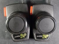
I only built one paddle (1 Meg pot) but it works fine with either player. I just bought ($18 including shipping) used generic paddles for an Atari 2600. AFAIK these use a 1 Meg pot. They have a single 9 pin connector and fire buttons on each paddle (for serving). This seems the better choice than attempting to make my own.

I am close to the dreaded off-the-breadboard onto a soldered board and enclosure.

Seems like this old board is the right one to use :)

20231012_162111.jpg
 
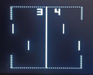
After lots of delays, I was able to get back to this project and actually have a "tah-da" moment.

pong screen 20231205_080245.jpg

My usual finished projects with enclosures look like a 5-year old made them and this one may be up to the 11-year old standard. There were no real difficulties but a couple of boneheaded mistakes that I eventually found and corrected. Everything works!

p1 20231205_080854.jpg
p2 20231205_080936.jpg

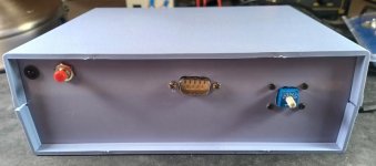
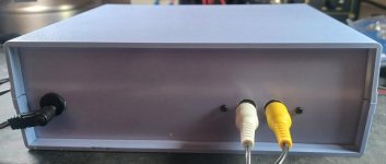
The switch on the right front (as much as I could, I used what I had throughout) selects the Game; Practice, Squash, Soccer, Tennis, Rifle games 1 & 2 (which I did not implement as I mentioned earlier). The 9-pin on the front connects to the paddles. I bought these, but despite cleaning extensively, they are pretty choppy and I may see if I can get some better ones). The RCA jacks on the back are for audio/video, and power on the left side..

pong paddles 20231205_081655.jpg

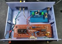
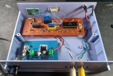
I did use the Archer board and the switches on the board control options; ball angles, ball speed, manual serve (pressing the paddle button starts the serve), and bat size. I had intended to make a power supply, and then I remembered that I had purchased a selection of these pre-made ones (5,6,12V) that were incredibly cheap, so I used one. Having a full bridge on them, I could make uses of a selection of old wall warts (you know, the negative tip, unregulated, AC, all the odd balls that I have saved for no particular reason)

p3 20231205_081021.jpg

p4 20231205_081048.jpg

I certainly could have done a neater job of soldering (notice that I am not showing a pic of the underside of the board), but hey it all works!

The Pong chip made in 1977 now works in 2023 and that's what I wanted to do. Good stuff.
 
The Archer protoboard adds just that little extra vibe to it. Pretty cool!

What does the red button on the left do? Reset? I can't quite follow where its wires end up on the board. The rotary DIP is a classy solution for selecting the game, too.
 
After lots of delays, I was able to get back to this project and actually have a "tah-da" moment.

View attachment 1269162

My usual finished projects with enclosures look like a 5-year old made them and this one may be up to the 11-year old standard. There were no real difficulties but a couple of boneheaded mistakes that I eventually found and corrected. Everything works!

View attachment 1269163
View attachment 1269164

The switch on the right front (as much as I could, I used what I had throughout) selects the Game; Practice, Squash, Soccer, Tennis, Rifle games 1 & 2 (which I did not implement as I mentioned earlier). The 9-pin on the front connects to the paddles. I bought these, but despite cleaning extensively, they are pretty choppy and I may see if I can get some better ones). The RCA jacks on the back are for audio/video, and power on the left side..

View attachment 1269165

I did use the Archer board and the switches on the board control options; ball angles, ball speed, manual serve (pressing the paddle button starts the serve), and bat size. I had intended to make a power supply, and then I remembered that I had purchased a selection of these pre-made ones (5,6,12V) that were incredibly cheap, so I used one. Having a full bridge on them, I could make uses of a selection of old wall warts (you know, the negative tip, unregulated, AC, all the odd balls that I have saved for no particular reason)

View attachment 1269166

View attachment 1269167

I certainly could have done a neater job of soldering (notice that I am not showing a pic of the underside of the board), but hey it all works!

The Pong chip made in 1977 now works in 2023 and that's what I wanted to do. Good stuff.
Nice job! I love everything about your build- using parts you already had, the old Archer/RS board, the re-purposed wall wart, (I have never thrown away a power supply, EVER, so I have like 30 of them) , the old school enclosure and of course mission itself. Classic hobby electronics project. Thank you for sharing this!
 
Back
Top