• Please review our updated Terms and Rules here

Bell & Howell Apple II - 'Darth Vader' - Astec Power Supply AA11040B no voltages

ArcadeDanger

New Member
Joined
Dec 31, 2023
Messages
5
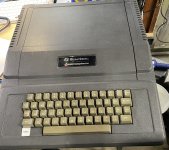
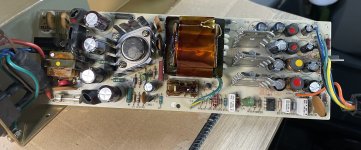
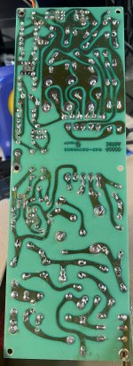
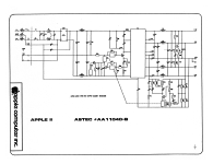
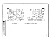
Hi everyone, I'm trying to get old Darth Vader Apple II running again and its power supply is giving me a hard time. No visible signs of life on power up. Took the power supply out, it is an Astec AA11040B. No voltages at any of the pins (+5,-5, +12 or -12) all dead on multimeter. Testing this with a multimeter between the ground and each wire in the connector.

Tried:
-Fuse tested ok.
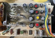
-Went through and did a cap kit and replaced the cracked RIFA (kit sourced from console5). No change. Note the capacitors I pulled were testing ok in the ESR with a few out of spec.
-Desoldered 1 leg and lifted to test all the diodes, tested all ok.
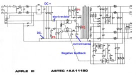
-Transistors Q1, Q3 were removed and tested outside of circuit, seem ok.
-Went through board looking for cold joints, nothing obvious but touched up anything remotely suspect.
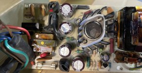
-IC1 (TL431CP) was replaced, original is ok - behaved same as replacement with diode tests, looks like a transistor but it's not, which is why it didn't test proper initially.
-T3 transformer was removed and continuity tested according to another post based on this thread: https://forum.vcfed.org/index.php?t...ply-aa11040b-ticking-problem-when-cold.57242/.
-Diodes D11, D5, D4 were removed and replaced with 1N4148s that I had in my stock (the old ones tested ok, so this was a shotgun replacement that wasn't needed but it was on this thread: https://tinkerdifferent.com/threads/apple-ii-astec-power-supply-aa11040b-low-voltage-repair.2876/).

I read that sometimes there needs to be load to make the voltage show, so I did try putting some load on the +5 and +12 connectors (89ohm resistor for both) but that had no effect.

I need some help to figure out what else to do diagnostically to get the supply working again rather than me stumbling around replacing components. I have access to an old slightly out of focus oscilloscope if that would help, but I need guidance on what to do with it.

Thanks!
 

Attachments

  • BellAndHowell-AppleII-Black.jpg
    BellAndHowell-AppleII-Black.jpg
    2.5 MB · Views: 18
  • Astec-AA11040B-Components.jpg
    Astec-AA11040B-Components.jpg
    2.3 MB · Views: 18
  • Astec-AA11040B-LowVoltageSection.jpg
    Astec-AA11040B-LowVoltageSection.jpg
    2.1 MB · Views: 17
  • Astec-AA11040B-HighVoltageSection.jpg
    Astec-AA11040B-HighVoltageSection.jpg
    2.4 MB · Views: 16
  • Astec-AA11040B-Solderside.jpg
    Astec-AA11040B-Solderside.jpg
    1.8 MB · Views: 17
I have one of those in a IIgs that was missing its PSU. It's a well-designed unit.

Did you verify that you are getting 120vac from the IEC connector? If not, the PSU won't start. The other thing that I tend to suspect with switching PSUs that seem entirely dead (after checking fuses) is to see if any capacitors are shorted.

This thread also might be useful: https://www.applefritter.com/content/apple-iie-astec-aa-11040b-power-supplies

- Alex
 
I'm not trying to be a naysayer here, but it never ceases to surprise me how incorrect approaches are used in an attempt to repair faulty items like switch mode power supplies (SMPS's) and VDU's in vintage computers.

Then people end up wondering why they get nowhere with the repairs.

Despite that fact that the people on You tube who were said to be "Geniuses" advised them what to do, and somebody sold the punter a re-capping kit.

Lets talk about what went wrong and then what is right:

1) What goes wrong first:

It appears that the usual M/O is that a person with a faulty SMPS or VDU searches the net. They come across all manner of videos telling them to replace capacitors and other parts because somebody else did it, and it appeared to work. Anecdotal reports of success, replacing parts in a shotgun manner. And now, surprise surprise, people even selling a capacitor ,diode and transistor replacement kits for very many models of SMPS and VDU's.

It is easy to be seduced by a solution which offers "hope" at a reasonable price.

And offers a solution where no thinking & study is required to find out what has actually gone wrong.

The better You-tubers also come up with a "showy production" too, and many success stories are claimed, but , where is the scientific method ? or even long term followup, well simply, it is not there.

The sad fact of the matter is that global replacements of parts is exactly what you do not want to do to end up with a successful repair, unless, that just happened by dumb luck, and as we all know (and Casino operators know) that method will not work for you in the long run.

2) What is right:

The reality is that to effectively repair many electronic circuits, you have to understand exactly how the circuit works and understand the operation of each component.

Specifically know what sort of waveforms and voltages and currents you will likely see at various circuit points. If not guesswork and hunches remain. Ultimately these red herrings can be quite destructive to the apparatus you are working on. Many replacement parts can be incorrect, sub-standard, not installed correctly, or there can be pcb damage in the process, adding to the complexity of the problem at hand. The bottom line is that a part should only be replaced when a test determines it is defective.

SMPS supply circuitry, like most circuitry, is straightforward with some exceptions (once you understand it that is). But if you don't have that understanding & familiarity, it can be a very steep learning curve and daunting, because you would have to familiarize yourself with the Physics of resistors, capacitors diodes, transistors, mosfets, transformers, magnetic & electric field energies, switchmode topology, power transfer and look up the data sheets of the IC's used in the unit, and that's before even starting on the specific circuit of the SMPS you are dealing with.

There are some good sections in Horowitz & Hill's book, the Art of Electronics on the topic of the SMPS and general electronics theory of course.

However, one other way, is to post the schematic on this Forum thread for all to see. Describe the points on the circuit that have been tested and mark those on the schematic with the test data and ask for help.

If you at least have a scope, and meter, various points in the circuit can be tested and in most cases, the cause of the fault can be discovered.

In terms of testing you can do on the board, these are divided into powered tests and unpowerd tests. In some cases unpowered test alone can get to the bottom of the issue and if not, the powered tests and scope are required.
 
Last edited:
I think one needs to take into consideration the amount of effort someone is willing to put into troubleshooting an old system. Many people don't want to expend the time, effort, and money to learn about how to troubleshoot let alone expend the financial resources.

Is replacing capacitors a shotgun approach? Certainly. But it's not without its benefits. Electrolytic capacitors dry out over time. Thus what was a functional system when put into storage could end up being non-functional when taken out of storage. While many things could be the culprit something that dries out with time is a good starting point. Then there's the risk of troubleshooting a device which has hazardous voltages. It's easy to replace capacitors because there are no voltages present. But troubleshooting? That often needs to be done on a live circuit. A circuit with voltages which can cause injury / death. One needs to know what they're doing or one can get hurt, killed, or at a minimum damage their equipment. As someone who is familiar with electronics (I have been working with electronics since my youth and I have an electronics degree) I am hesitant to work on one of these power supplies (I have one sitting in the basement just waiting for me to troubleshoot but I keep putting it off because I am nervous about doing so).

There's also the issue of documentation or, more appropriately, lack of it. I recently had a Packard Bell power supply which was putting out around 10 volts on the 12 volt rail. I wanted to troubleshoot it but couldn't find any schematics. Upon inspection I saw leaking capacitors and decided to replace them. After having done so the power supply is working fine and I know it's good for many tens of years of operation.

So in the end I understand what you are saying and, if someone has the knowledge, skill, and tools to do proper troubleshooting then I think that is the best course of action. But blindly replacing capacitors has been known to fix bad power supplies too and, for someone who lacks the knowledge, skill, or tools to do proper troubleshooting it's not the worse thing they could do.
 
So in the end I understand what you are saying and, if someone has the knowledge, skill, and tools to do proper troubleshooting then I think that is the best course of action. But blindly replacing capacitors has been known to fix bad power supplies too and, for someone who lacks the knowledge, skill, or tools to do proper troubleshooting it's not the worse thing they could do.
Probably not the worst thing I agree. Randomly replacing IC's and other semiconductors is worse.

And as I mentioned recently on another thread, there are many people who defend the idea of global re-capping father than fault finding.

Often the remark is something like "I find that re-capping these units fixes the unit at least 80% of the time" . Though of course , a lot like at the Horse track, people tend to remember their wins, and suppress the bad outcomes in their minds so it could well be <50%. Also, consistent with that, it seems interesting how many people appear to find themselves in the bottom 20% and end up on Forums when global re-capping has not cured their woes.

You are right to be cautious about high voltages and live circuits, however, if you take suitable precautions not to connect yourself to them, the risks are significantly mitigated. And using an isolating transformer to power the primary side if you are connecting scopes, or better still a special isolated scope like a Tek 222PS. For those who are really concerned with cardiac issues and have implantable electronic devices, its not a bad idea to use double surgical gloves, especially working on line power & Tube based gear.

Also, there is no reason why you cannot copy the schematic out from the board itself.

I did this for the entire IBM-5155 switch-mode supply (the manufacturers published nothing) and also drew out the board's component layout and I've done it for many other boards without schematics, including entire VDU's and PWM motor control systems, printer interfaces etc. It really all depends on how prepared you are to work hard, and how determined you are to understand the circuit you are working on and effect repairs on it.

It is getting worse actually, historically many manufacturers provided schematics, they are becoming rare in modern times.


One you have the schematic and you have an Electronics Degree, as you do, (I'm not sure of the OP's skills here) you should be more than capable of working out the operating theory of the circuit. And once you have that in mind, testing various circuit points either powered or un-powered, it becomes clearer where the fault/s reside.

The OP's power supply looks like a very simple one. Have the schematics been found or copied out yet ?
 
Last edited:
Often the remark is something like "I find that re-capping these units fixes the unit at least 80% of the time" . Though of course , a lot like at the Horse track, people tend to remember their wins, and suppress the bad outcomes in their minds so it could well be <50%. Also, consistent with that, it seems interesting how many people appear to find themselves in the bottom 20% and end up on Forums when global re-capping has not cured their woes.

I am not sure I agree with this. For people who repair the same thing over and over and over again they start recognize certain things fail more than others. RAM is a prime example. I have performed troubleshooting on a few dozed Apple II (II, II+, IIe, and IIc) systems. One thing that pops up on a routine basis is one or more bad RAM chips. I would say nine times out of ten if I have a system that boots to a garbled screen RAM is the culprit.

Also, there is no reason why you cannot copy the schematic out from the board itself.

I did this for the entire IBM-5155 switch-mode supply (the manufacturers published nothing) and also drew out the board's component layout and I've done it for many other boards without schematics, including entire VDU's and PWM motor control systems, printer interfaces etc. It really all depends on how prepared you are to work hard, and how determined you are to understand the circuit you are working on and effect repairs on it.

This right here is the problem. A lot of these people aren't willing to put in a lot of time and effort to do this work, at least maybe not initially. Why spend hours upon hours doing this work when replacing capacitors is, relatively speaking, much easier and faster?

The OP's power supply looks like a very simple one. Have the schematics been found or copied out yet ?

Yes, the schematics are readily available. The documentation also includes some limited theory of operation information.
 
I don't disagree with you, Hugo, it is always best to actually determine the fault and work from there. I do feel that unless you're doing lots of repairs on devices of the same type, there is a hard learning curve each time to deeply learn the kit to know what's going on, so try the easy approach first and then do a deeper dive as needed.

I've repaired quite a few arcade CRT monitors, arcade PCBs and other electronics over the last few decades. Shotgun on capacitors has been a great method to get 80s and 90s electronics working again. It hasn't fixed everything every time, as you point out. However, I've never had a situation where replacing the capacitors made something worse, unless we're talking about damaging PCBs/lifted traces and such.

Where I am right now with the above mentioned power supply - replaced the capacitors (I kept the originals, they measured ESR ok and can put them back if that's recommended), continuity checked the T3 transformer, and checked the transistors and diodes out of circuit. There's something else beyond my current capacity and that's why I'm reaching out to get instructions on how to continue deeper debugging with the means I have (oscilloscope available, logic probe and multimeter) and I prefer to explain what has been tried in detail.

My preference is to keep as much of the original hardware as possible.

I did measure 115VAC at the entry point to the high voltage section, so the connector/fuse seem to be ok. I need to know where else to put the probes next.


The Astec documents I'm referring to are hosted here: https://ia800908.us.archive.org/15/items/Astec_Power_Supplies_Aug82/Astec_Power_Supplies_Aug82.pdf

The doc is a little heavy with all the variations so I extracted the ones relevant to the one I'm working on and attached to the thread here.
 

Attachments

  • Astec-AA11040B-Schematic.png
    Astec-AA11040B-Schematic.png
    1.4 MB · Views: 5
  • Astec-AA11040B-PCBLayout.png
    Astec-AA11040B-PCBLayout.png
    1.2 MB · Views: 5
  • Astec-AA11040B-PartsList.pdf
    1 MB · Views: 2
Ok, with the schematics you can start some work. The actual schematic for the B unit is a sloppy drawing with the boxes not conveying the operating theory.

Since the basic design of the AA11190 circuit is the same on the primary (line side) and the negative feedback pathway, its better to use that for now and apply any ideas to the other AA11040B schematic. So the parts I'm referring to are for this attached circuit.It would pay to print it out.

I have attached it with just a few initial things to discuss on the operating theory and a couple of tests to do.

Firstly, notice the way they organised the 115/230V option. In the 230V case the arrangement is a full wave bridge rectifier , and in the 115V case it is a half wave voltage doubler, just with the closure of one switch (clever isn't that?)

I assume you are running off 115V, but it doesn't matter because in both cases (provided the switch matches the line voltage) there will be about 300 to 320V DC across points DC+ and DC- you can check that with your meter with the unit powered.

(the rail labelled as DC- is the "common negative rail" for the primary circuit)

The primary circuit is fairly basic. It is a transistor oscillator based on power transistor Q2. When power is initially applied, this generates base current for Q2 via the start resistor R1 (Check this and resistor R2 are not open on an un-powered test.

The collector current of Q2 then energizes the primary windng P1. This induces a voltage in the secondary winding P3. If you look at the polarities of these windings you will see that the voltage developed across winding P3, with respect to common (the side without the dot) has a positive going polarity (the opposite polarity that transistor Q2 is applying to the primary windingP1). Then current flows via R4, C-10 & T3 winding back to the base circuit of Q2, reinforcing the conduction of Q2, this causes Q2 to go into a saturated switching condition, when its collector to emitter voltage drops very low.

We now have the 320V DC switched across the primary P1 of the main transformer P1. This state cannot persist for a few reasons.

The voltage induced across a transformer winding is proportional to the rate of change of current with time. And the rate will fall off as the core begins saturation the induced voltage across P3 will fall away. Anther reason would be that as Q2's emitter current develops a voltage across R12, then via R10 & R7 it drives the base of Q1, this shunts Q2's base drive causing Q2 to start to cut off.

Therefore, even without any negative feedback via T3 from the secondary system of T2, Q2, after a while would cut off. When Q2 does cut off it does it rapidly because the field in the main transformer starts to collapse and the voltage across its terminals reverse as does the induced voltage across P3.

Then the process repeats and you have Q2 applying a square like wave drive applied to the primary winding P1.

The idea of the additional winding P2 is to damp the field collapse via D3 and control the rate the field collapses when Q2 is turned off and prevent a large positive going voltage spike on the collector of Q2 destroying it.

It is the duty cycle of the oscillator that is Q2 , determines what the output voltages will be on the secondary of T2.

It is Q1's job to control or reduce that duty cycle, either by detecting over-current via the current sense resistor R12, or by receiving a negative feedback signal from the secondary side of the supply via T3 (T3 provides isolation from the secondary side of the supply to the primary, some PSU's use opto-couplers instead)

The first questions, therefore, confronted by a PSU with no output :

Is the DC voltage present on the primary circuit ?

Is the primary circuit complete (the resistor in series with P1 not open) Output transistor ok, current sense resistor and other emitter resistor and diode not open ?

Is the transistor receiving its start up base current is R2 and R3 ok ?

Is the feedback pathway P3, R4 and C10 and secondary winding of T3 ok ? And Q2's base inductor and resistor OK ?

If Q1 was shorted, or D4 shorted this would kill Q2's base drive so check that too.

Therefore if all of the above is in fact ok, then the primary circuit should be oscillating. That is the next thing to determine. This can be done by powering the supply via a Line isolating transformer and using a x10 scope probe (but a x100 is better to protect the scope and probe as sometimes the peak voltage here can be over 400V) with the scopes earth clip on DC- (common) and the probe tip on the collector of Q2. Don't attempt it without the isolating transformer, it must be isolating type, not an auto-transformer.

A lot of the time though, you can avoid using the scope on the primary (live) side to check for oscillation and simply use it on the secondary side of the main transformer, were the voltages are scaled down and isolated too. A meter on the primary side is ok as it is a two terminal instrument and completely isolated.

For example, it could possibly still be oscillating, with a duty cycle that is so narrow that there is negligible voltage on the secondary.

If the SCR crowbar circuit is triggering on/immediately after power up (which can happen if a suitable dummy load isn't applied to the supply's +12V output and COM terminals) or the SCR or its gate circuit defective. The shunting effect is so significant on the transformer secondaries, it completely kills the induced voltage across winding P3. The oscillations are terminated, and Q2's collector current remains a low value, due to the low base current of the start up resistor.

This effect was one of the things that made self-oscillating DC:DC converters attractive. If the output gets shorted out, the oscillations driving the primary are extinguished so they are self short circuit protected.

A question: If you have checked the transistors Q1 and Q2 and Q3 and Q4 and the SCR for that matter ...how did you check them?

And what have you been using for the Dummy load?
 

Attachments

  • PSU1.jpg
    PSU1.jpg
    125.2 KB · Views: 5
Last edited:
Ok, with the schematics you can start some work. The actual schematic for the B unit is a sloppy drawing with the boxes not conveying the operating theory.

Since the basic design of the AA11190 circuit is the same on the primary (line side) and the negative feedback pathway, its better to use that for now and apply any ideas to the other AA11040B schematic. So the parts I'm referring to are for this attached circuit.It would pay to print it out.

I have attached it with just a few initial things to discuss on the operating theory and a couple of tests to do.

Firstly, notice the way they organised the 115/230V option. In the 230V case the arrangement is a full wave bridge rectifier , and in the 115V case it is a half wave voltage doubler, just with the closure of one switch (clever isn't that?)

I assume you are running off 115V, but it doesn't matter because in both cases (provided the switch matches the line voltage) there will be about 300 to 320V DC across points DC+ and DC- you can check that with your meter with the unit powered.

(the rail labelled as DC- is the "common negative rail" for the primary circuit)

The primary circuit is fairly basic. It is a transistor oscillator based on power transistor Q2. When power is initially applied, this generates base current for Q2 via the start resistor R1 (Check this and resistor R2 are not open on an un-powered test.

The collector current of Q2 then energizes the primary windng P1. This induces a voltage in the secondary winding P3. If you look at the polarities of these windings you will see that the voltage developed across winding P3, with respect to common (the side without the dot) has a positive going polarity (the opposite polarity that transistor Q2 is applying to the primary windingP1). Then current flows via R4, C-10 & T3 winding back to the base circuit of Q2, reinforcing the conduction of Q2, this causes Q2 to go into a saturated switching condition, when its collector to emitter voltage drops very low.

We now have the 320V DC switched across the primary P1 of the main transformer P1. This state cannot persist for a few reasons.

The voltage induced across a transformer winding is proportional to the rate of change of current with time. And the rate will fall off as the core begins saturation the induced voltage across P3 will fall away. Anther reason would be that as Q2's emitter current develops a voltage across R12, then via R10 & R7 it drives the base of Q1, this shunts Q2's base drive causing Q2 to start to cut off.

Therefore, even without any negative feedback via T3 from the secondary system of T2, Q2, after a while would cut off. When Q2 does cut off it does it rapidly because the field in the main transformer starts to collapse and the voltage across its terminals reverse as does the induced voltage across P3.

Then the process repeats and you have Q2 applying a square like wave drive applied to the primary winding P1.

The idea of the additional winding P2 is to damp the field collapse via D3 and control the rate the field collapses when Q2 is turned off and prevent a large positive going voltage spike on the collector of Q2 destroying it.

It is the duty cycle of the oscillator that is Q2 , determines what the output voltages will be on the secondary of T2.

It is Q1's job to control or reduce that duty cycle, either by detecting over-current via the current sense resistor R12, or by receiving a negative feedback signal from the secondary side of the supply via T3 (T3 provides isolation from the secondary side of the supply to the primary, some PSU's use opto-couplers instead)

The first questions, therefore, confronted by a PSU with no output :

Is the DC voltage present on the primary circuit ?

Is the primary circuit complete (the resistor in series with P1 not open) Output transistor ok, current sense resistor and other emitter resistor and diode not open ?

Is the transistor receiving its start up base current is R2 and R3 ok ?

Is the feedback pathway P3, R4 and C10 and secondary winding of T3 ok ? And Q2's base inductor and resistor OK ?

If Q1 was shorted, or D4 shorted this would kill Q2's base drive so check that too.

Therefore if all of the above is in fact ok, then the primary circuit should be oscillating. That is the next thing to determine. This can be done by powering the supply via a Line isolating transformer and using a x10 scope probe (but a x100 is better to protect the scope and probe as sometimes the peak voltage here can be over 400V) with the scopes earth clip on DC- (common) and the probe tip on the collector of Q2. Don't attempt it without the isolating transformer, it must be isolating type, not an auto-transformer.

A lot of the time though, you can avoid using the scope on the primary (live) side to check for oscillation and simply use it on the secondary side of the main transformer, were the voltages are scaled down and isolated too. A meter on the primary side is ok as it is a two terminal instrument and completely isolated.

For example, it could possibly still be oscillating, with a duty cycle that is so narrow that there is negligible voltage on the secondary.

If the SCR crowbar circuit is triggering on/immediately after power up (which can happen if a suitable dummy load isn't applied to the supply's +12V output and COM terminals) or the SCR or its gate circuit defective. The shunting effect is so significant on the transformer secondaries, it completely kills the induced voltage across winding P3. The oscillations are terminated, and Q2's collector current remains a low value, due to the low base current of the start up resistor.

This effect was one of the things that made self-oscillating DC:DC converters attractive. If the output gets shorted out, the oscillations driving the primary are extinguished so they are self short circuit protected.

A question: If you have checked the transistors Q1 and Q2 and Q3 and Q4 and the SCR for that matter ...how did you check them?

And what have you been using for the Dummy load?
Wanted to thank you for this explanation as I will be troubleshooting one of these power supplies too and I will definitely benefit from this information.
 
Back
Top