• Please review our updated Terms and Rules here

Brightness not uniform - Apple //c momo CRT monitor

offensive_Jerk

Veteran Member
Joined
Jul 13, 2009
Messages
1,226
Location
Wisconsin
Got this untested and of course it was packed like garbage.

When I power it on with no signal and brightness up, about 2/3 of the screen is green, the rest is black. I plugged in a PS2 and same thing. The text on the right of the screen looks bad too.

Seems like the brightness is not affecting the whole CRT.

What can I look for to fix this?
 

Attachments

  • PXL_20230921_171315277.MP.jpg
    PXL_20230921_171315277.MP.jpg
    2.8 MB · Views: 27
  • PXL_20230921_164551908.MP.jpg
    PXL_20230921_164551908.MP.jpg
    3.1 MB · Views: 26
The slanted wide bar is probably an artifact of the camera photo.. Is that correct, or not, if so you should say so.

I assume what you are referring to is that the R side of the scanning raster is fading out, is this correct ? If so likely there is a problem in the H blanking.

Can you post the schematic for this VDU ?
Yes the slanted bar is an artifact of the camera, but it still shows how the right part of the screen is very dark. I'll see if I can find schematic.
 
Could you try a more detailed test image? It sort of looks like the width is wrong and the image is wrapping at the edge of the screen.

Also, just be aware that image centering on these monitors may differ a bit when used on other composite video sources instead of a genuine Apple //c.
 
The first thing is to find out, whether what you are seeing (or not seeing in this case) represents the scanning raster being off center as in a scanning fault, or the CRT beam being blanked off on the Right side, with the raster present.

One quick way to tell is to turn the brightness up to full and see if the raster appears on the R or not.

I'm suspicious of a blanking issue because the edge of the dark area is fuzzy looking and fades over a some microseconds, normally if it was the raster edge, from an offset scan, the edge seen is very sharp.In addition to this, the left edge of the raster is visible, just I think at the start of the scan just, which it would not be if the entire H scan was offset to the left.

Where is the schematic ?

A known test pattern image also helps, in other words a known good signal. I think this VDU accepts a fairly close to standard syncs of the NTSC system, but monochrome signal. So a TV signal generator might help.
 
Last edited:
Some of the CRT's electron gun voltages are usually sourced from various secondary windings on the flyback. An open cap there will cause one side of the picture to fade out like that. Look for something in the 4.7-33uF range at 160-350v near the flyback, or on the CRT socket board.
 
I did find this:
Sams manual
They are very large files to download and don't view well as one sheet. If you can identify the correct one and post it as an image file attachment, it will help with suggestions of where to test.

Have you tried increasing the brightness to full to see if there is a raster scan in the dark area, or not ?

For the beam to go dim dynamically, it would require that either That the CRT's grid voltage was dropping or the cathode going positive (unlikely with failing capacitors) or the CRT's A1 anode voltage dropping with H rate ripple, all these can be checked with the scope. But it looks a little too sudden, suggesting a blanking issue but the schematic will help. Not all sets used H blanking. If it is there it is often taken from the H output stage and mixed in at the video driver or output stage.
 
The picture on the right is the monitor with the brightness all the way with no signal. The right part of the screen is dark with the brightness all the way up.
 
I think it is a case where you will need to scope, with a x10 probe, 50v/cm, the CRT's grid, cathode and A1 voltages. You could lock ch1 of the scope to the H sync, and check with ch 2, to see if the CRT's electrode voltages are stable over the course of the H scan, or not. If they are, then there must be something affecting the scanning raster on the right.

Unfortunately if the CRT beam is heavily blanked, even the max brightness control test may not illuminate the screen, making that test inconclusive, whether the raster scan is present on the right, or not. However, I'm pretty sure I can see the L side edge of the raster scan, this is generated from energy stored on the R side of the raster. So, even though we cannot see it because something is blanking the CRT's beam, I'm pretty sure the R side of the raster is there (normal H deflection).

One other possibility, but unlikely, that something is physically obstructing the beam, but, when that happens you normally would not have the straight vertical edge, so that is unlikely, it is more likely an electrical issue affecting the CRT's beam current.
 
Last edited:
Crap, I don't have a scope.
Well, you are flying blind, or in a deep underground cave with no light, feeling your way along the walls, hoping to find an exit.

Very experienced Techs can find many faults with simple tools like logic probes & meters, but a lot of the time, it works out as luck, rather than by good scope measurements and study of the test data.

Obviously, to fault find efficiently, it requires an understanding of how the circuit you are working on works. If not, hunches and guesses come into play which can lead to parts being needless replaced, additional faults introduced and damage to the apparatus.
 
I could add there are some "tricks" that could get to the bottom of it, without a scope.

One is to experimentally add capacitance, of a similar value to the existing filter capacitors by adding them in parallel to the exiting ones one by one on the circuits that filter the supply voltage for the video output stage and CRT. The other is, to increase the A1 voltage with a sub brightness control (if there is one), If the raster lights up the another capacitor can be used too shunt out the video signal, to see if the step disturbance is actually in the video signal chain. None of this though, is anywhere as good as checking things with the scope. It is one of those methods that you would do stranded on a desert island or Lost in Space.

Scopes have become so cheap now, if you plan on fixing even one or two items of vintage computer gear, you may as well get one.
Can you recommend one?
 
Can you recommend one?
That is a good question.

There are many digital models now. So you will get a lot of recommendations.

If you are starting out though, using a scope for the first time, you are more likely to get yourself into trouble using a digital scope. Sample rate issues affect the data, settings in drop down on screen menus that you are not familiar with etc.

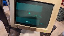
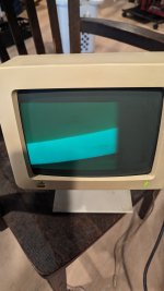
I always recommend starting out with an analog scope with a CRT in it, where all(most) of the controls are intuitive, and you never see things on the display that can mislead you which can happen with a digital scope. Move to a digital scope after the the analog one is mastered.

The benefits of digital scopes though are data storage & transfer, math functions, cursors (though some analog scopes have these). But of course, when you just want to observe an electrical waveform changing over time (unless it is very slow), for the purpose of diagnosis and repair, you don't need all those bells and whistles. Ideally the scope would have the equivalent of a 20MHz bandwidth or better for general repairs, computers, VDU's etc. Better 50 or 100MHz though. (My favorite scope is the Tek 2456B, 400MHz, but you wouldn't want that as a starter scope).

B&K made some good analog scopes, like this 30MHz unit, and interestingly they turn up like this unused, this would be a very good starter scope to learn with and diagnose faults in VDU's, just buy a couple of x10 probes to go with it:


(seems an amazing buy because essentially the same scope is available new at Newark for just on $1000.)

Probably worth the price as new. One problem with used analog scopes, many are hammered, abused, and look like they have been thrown in and out of the backs of service trucks. So while you could get a used one for $100 or less, its probably is not worth it. Unless it is in exceptional cosmetic condition, loved by its previous one owner, and known to be working.

This Tenma scope looks good too, its cheaper:


100MHz probes work fine, they have a compensation capacitor on their plug and you match them up tho the scope on a square wave test:


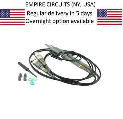
Also if you connect the x10 probe to a part of a circuit with over 500 to 600V on it, its bad for the probe and scope input amplifiers, so to avoid accidents a x100 probe is helpful working on VDU's or tube gear, for example, in a color VDU, you could have 1200V peak on the collector of the H output transistor, and want to look at that with your scope:

This sort of thing which is good for 2kV:

 
Last edited:
I noticed several people were having trouble finding the schematics for this version of the //c monochrome monitor..

I have a spare nos board for the a2m6016 12" mono monitor and the layout appears very similar.

Perhaps it's basically a cut down version of this PCB
 

Attachments

  • Apple_Monitor_II_Main_Schematic_050-5020-A.pdf
    386.5 KB · Views: 1
Back
Top