• Please review our updated Terms and Rules here

Building a Commodore 1581 floppy drive from scratch

VintageVic

Experienced Member
Joined
Dec 9, 2019
Messages
340
Location
Finland
Yes,

this has been done before. Now I took the challenge if I'm able to do it again.

Not only that, but I decided to make a youtube mini series of the project.
That takes another set of skills which I need to learn. So here goes part one:


I hope it is entertaining despite my Finnish accent and other little lackings.
 
"There's always an extra hand when you don't need one". LOL. That part was awesome.
<salute> for the great project!

I am deadly with a soldering iron (I don't get why I'm so terrible, but... ). I went a third path, which is to order a new FNX1591 (1581 compatible) from Foenix Retro Systems. At $275, it's not cheap, but it's cheaper than eBay and it's supporting a creator of new retro stuff. and I don't have to do anything other than upload the ROM I want for it (C=, JiffyDOS, etc.) https://c256foenix.com/product/fnx1591/?v=7516fd43adaa
 
Yes,

this has been done before. Now I took the challenge if I'm able to do it again.

Not only that, but I decided to make a youtube mini series of the project.
That takes another set of skills which I need to learn. So here goes part one:


I hope it is entertaining despite my Finnish accent and other little lackings.
Funny you should mention that. I just saw these 3D printed shells at the consignment area of VCF East (I couldnt see a pcb though, possible inside?) for $75.00 to build your own 1581. Was really pricey and I couldnt see a PCB so seems I and everyone else passed. But building one now seems the best and most cost effective way to go
 
Yes,

this has been done before. Now I took the challenge if I'm able to do it again.

Not only that, but I decided to make a youtube mini series of the project.
That takes another set of skills which I need to learn. So here goes part one:


I hope it is entertaining despite my Finnish accent and other little lackings.
Yea, I did this project to, it is actually a neat little one, and kinda fun given the price of the real 1581's. I also saw a case mold for a 1582 (double 1581) and I kinda want to make two boards now for that, hard code them drives 8 and 9 and change them to 10 and 11 with a switch flip.
 
Yes,

this has been done before. Now I took the challenge if I'm able to do it again.

Not only that, but I decided to make a youtube mini series of the project.

I'll be watching this series. Good luck! It looks like a good start to the project.
 
Thanks for all of your comments!

I noticed my video in youtube was rather low quality. I will later try to re-edit it with a bit higher resolution.

But for now, back to the project. I finally received all the rest of the components. Well, all but the crystal.
I grew tired of waiting for that so I pulled 16mhz crystal from donor 1541 pcb.

Everything seems to be in place, but the 1581 pcb does not appear to boot. Both LEDs are lit and stay that
way. A bit expected that some amount of troubleshooting is needed here.

I started with testing the bigger ICs. I have a working 1571 drive. Pulled it's CPU and 1772 motor controller IC.
Installed IC sockets and tested the both cpu and 1772 and they are working in the 1571 drive. I also doublechecked
that the ROM of the 1581 still has the data that I have saved there.

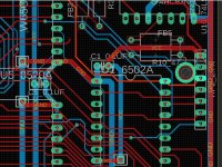
Perhaps an error in the replica pcb. Before continuing the checking with ICs, I measured voltages of every chip. They
do have a good +5.09V and all of the chips also have firm gnd contact. Then I noticed that the reset line is low.
When powered up, voltage goes from 0 to 0.12V in the reset line. That was strange. I started to check logic
inputs of the reset line components and noticed that U12 (7604 hex inverter) had one input equal to output (low).
Further checking U12 I noticed that U12 legs 10 and 12 were shorted. Further investigation revealed the short near
RP2 and through hole. Another mistake by me during Eagle designing the board.

I made a few cuts to the through hole to sever the short. Had to do it from both sides of the pcb obviously.
Now reset line behaviour chanced. During power on, the reset line goes to +5V and stays there (it is supposed
to stay up, right? Or not?).

However, the 1581 replica board will still not boot. CPU, 6526A and the 1772 gets warm rather soon, almost hot.
There is yet another issue with the pcb and/or some of the ICs or components. Troubleshooting continues.
 

Attachments

  • short_in_RP2.jpg
    short_in_RP2.jpg
    251.2 KB · Views: 4
Let's briefly revisit this 1581 building project.
I've had a break from it, probably about 6 months, due to summer works (such as rebuilding the roof of my house and making firewoods for the winter).

During my break, I did tested an idea here and there, but it was TOUGH figuring out what was wrong with
the pcb! I had numerous problems, at least a dozen. A few traces in the pcb were shorted to where they were not supposed
to be shorted. Missing gnd traces from some ICs, or completely missing traces between IC's. At least one misinterpretation from the shcematics
near CR diode in the reset line.

Fair amount of frustration was involved and yet, very fun and educational project. I'd say to start from absolutely scratch, the diffifulty level is
rather high. And for now, I'm getting into the more fun part of it! Eventually I got issues sorted with the pcb and got it to boot. Oh the joy there
to see it boot!

Still, there were issues to get ibm pc drive mechanics to work with commodore 1581 pcb. I found 'how to' guide from some 80s or 90s from
Ray Carlsens site. It did not go smoothly either. The guide is not perfect and it has at least one error (mentions connection to floppy cable pin3 when
it is referring to pin2 of the cable). The guide lacks also discussion if you are using straight or twisted floppy cable.

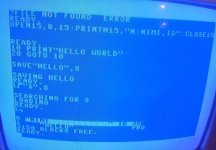
But for now, I was -mostly- able to sort the issues with the drive as well! My first format attempt failed. Command did went thrue and it seemed
to format the floppy disc, but the disc was not readable anyway. I tried to format another disc and this time it did work! I know both discs are good,
previously having IBM pc format. So, I suspect, there is probably some issue between the mechanics and the pcb. Mostly I suspect this is an issue
with the ready signal. I'm pulling ready signal to gnd on the pcb. If the mechanics was not ready, in my first format attempt then maybe that's why
the format failed (?).

Anyway. This is my current state of the build. I'm considering making part2 of the build video from here on. I have not yet started to build
casing for the drive. It will be built on old / nonfunctional 1541 case that I have lying around.
 

Attachments

  • format.jpg
    format.jpg
    124.3 KB · Views: 8
Great project! So nice to see that you got it working!

I've had a similar plan with a 8050 drive. The PCB is so old and cracked that I have given up on it. But drawing a new PCB it certainly a daunting task.
 
Great project! So nice to see that you got it working!

I've had a similar plan with a 8050 drive. The PCB is so old and cracked that I have given up on it. But drawing a new PCB it certainly a daunting task.
It might not be.

If your original pcb is very badly damaged and is basically trash, it is actually a dream come true.

After documenting the components, simply remove them all, and place the PCB in a scanner.

Then it is a piece of cake to trace over it in a drawing program using the transparency option (I just use the vintage Microsoft Picture It), then you delete that background later. You can also add to the transparency a 2.54mm grid (because for most vintage pcb's that is what was used and its typical for the IC pin spacing too).

Many pcb houses now will replicate the pcb for you from just a .jpg image you draw it, and if you give them the dimensions, this is also where the 2.54mm grid helps. (Two examples LD Electronics in Australia will do it, or Storm Circuit in Shenzhen).

I have done this to replicate a number of pcb's, and it would have been a total luxury to have an exact size pcb scan, a lot of the time I had to use photos, which contained various forms of geometrical distortion.
 
Back
Top