• Please review our updated Terms and Rules here

Building my own ZX80

Ben M

Member
Joined
Jul 27, 2024
Messages
31
Hello,

I started with building an ZX80 a while ago. I always wanted to build an Apple 1, but it is a very expensive project. So I thought about building my own ZX80.

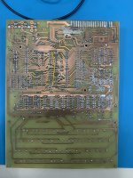
At the moment, I made my own pcb (from Grand: http://searle.x10host.com/zx80/zx80.html)

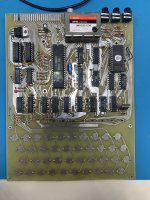
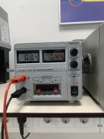
A couple of days ago, i connected it for the first time to an external PSU. After checking the pcb for shorts etc. It seemed safe. And it was (luckily). The current consumption at 9V is around 440mA. That seems not to bad. The 7805 gets warm quickly (I do not have a heatsink attached yet), and the rom/ram and cpu are getting a bit warm. But not out of the ordinary. The logic gates are mostly just cold.

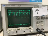
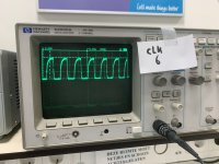
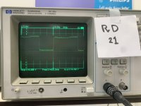
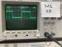
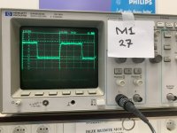
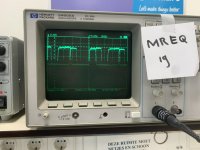
But besides Al that. The voltage level seems alright. The IC’s all getting around 4.9V. When using the scope, the 5V is a bit messy, but not that bad in my opinion. The frequency from the crystal is around 6.55 mhz and the clock signal at the CPU is around 3.255, it’s a bit low, but I don’t know if that can give problems. It should be 3.5 if I’m right.

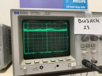
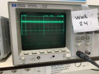
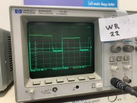
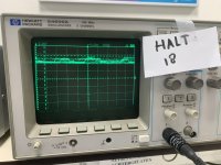
I measured the signal at the “HALT” pin at the cpu. I get mostly weird signals. Not nice high and low pulses. But sometimes it seems that a logic gate doesn’t go low. But around 3/4 volts. (I think I have to check ground overall).

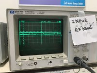
When I connect an old Composite monitor at the video/sync before the Rf modulator, I get some weird snow look a like at the monitor. So there is some signal. But it’s not good.

But I can continue at the end of the week with the project. I’m curious about the influence of the low clock signal. If it can effect the operation?

I will try to provide some pictures (from the signals at the end of the week.

Regards, Ben
 
If you have a 6.5 MHz crystal, the CPU clock is divided by 2 to give 3.25 MHz for the CPU.

If you measure 6.55 MHz from the crystal oscillator circuit, then the CPU clock should be 3.275 MHz (which appears to be what you measure).

As a result, the circuit is working as expected. In fact, the website mentions 3.25 MHz, so where did you read 3.5 MHz at?

Yes, if you can post some of the Z80 control signals at some point, that would be useful with fault finding.

/MREQ, /M1, /RD, /INT and /RFSH would be useful.

I see /NMI, /BUSREQ and /WAIT are all pulled up to +5V via resistors, so should not affect the operation of the machine (i.e. if you monitor these signals, they should always be HIGH.

Yes, you need a heatsink on the +5V regulator...

I will have to reacquaint myself with the ZX80 operation... This takes me back :)!

Dave
 
Are you sure the z80 is good? Where did you get it from? I've seen a LOT of z80s lately that don't seem to do anything when reset. If a z80 has power, clock and no stray signals, NMI, INT and BUSREQ and WAIT are all high, and it is reset ( low to high on RST) then it will start to generate addresses from 0000 and read with M1 from the ROM. The ROM select should also be pulsing from the decode logic.

If it's not doing that, there's a real possibility the z80 is faulty if you ordered it from a Chinese seller or Ebay. Does it look new? Do you have a microscope to look at whether the text appears written with a laser or masked?

A logic analyzer might help. You should be looking for address 0000 and read/m1/mreq all low, and the ROM putting the first byte onto the data bus.
 
Thank you for your reply Dave!

You are right, I did not notice it right. So that is one problem less .

I have never really “analysed” cpu signals etc. I study electrical engineering, but now it’s mostly focused on power electronics ;) So it’s all a bit new for me.

My lecture was finished early today, so I went to the lab and made some pictures of the signals I could measure on the different cpu pins you spoke about.

It’s a digital oscilloscope, but with a CRT, so the pictures are not always that clear. But I hope it is good enough. I put a piece of paper next to it, so it’s easy to see which pin it is.
 

Attachments

  • IMG_8074.jpeg
    IMG_8074.jpeg
    1.8 MB · Views: 27
  • IMG_8073.jpeg
    IMG_8073.jpeg
    1.9 MB · Views: 24
  • IMG_8072.jpeg
    IMG_8072.jpeg
    1 MB · Views: 23
  • IMG_8070.jpeg
    IMG_8070.jpeg
    1.9 MB · Views: 18
  • IMG_8069.jpeg
    IMG_8069.jpeg
    2 MB · Views: 19
  • IMG_8066.jpeg
    IMG_8066.jpeg
    2 MB · Views: 19
  • IMG_8065.jpeg
    IMG_8065.jpeg
    2 MB · Views: 20
  • IMG_8064.jpeg
    IMG_8064.jpeg
    2 MB · Views: 17
  • IMG_8063.jpeg
    IMG_8063.jpeg
    1.9 MB · Views: 16
  • IMG_8062.jpeg
    IMG_8062.jpeg
    2 MB · Views: 22
The rest of the pictures:
 

Attachments

  • IMG_8059.jpeg
    IMG_8059.jpeg
    2 MB · Views: 7
  • IMG_8058.jpeg
    IMG_8058.jpeg
    1.9 MB · Views: 6
  • IMG_8057.jpeg
    IMG_8057.jpeg
    2 MB · Views: 6
  • IMG_8056.jpeg
    IMG_8056.jpeg
    2 MB · Views: 7
  • IMG_8054.jpeg
    IMG_8054.jpeg
    2 MB · Views: 5
  • IMG_8053.jpeg
    IMG_8053.jpeg
    2 MB · Views: 6
Are you sure the z80 is good? Where did you get it from? I've seen a LOT of z80s lately that don't seem to do anything when reset. If a z80 has power, clock and no stray signals, NMI, INT and BUSREQ and WAIT are all high, and it is reset ( low to high on RST) then it will start to generate addresses from 0000 and read with M1 from the ROM. The ROM select should also be pulsing from the decode logic.

If it's not doing that, there's a real possibility the z80 is faulty if you ordered it from a Chinese seller or Ebay. Does it look new? Do you have a microscope to look at whether the text appears written with a laser or masked?

A logic analyzer might help. You should be looking for address 0000 and read/m1/mreq all low, and the ROM putting the first byte onto the data bus.
Thanks for your reply,

I have not tested it, but I bought it from a small online webshop where in the Netherlands. It’s from a guy that has his own little shop. It was tested if i remember. It’s a NEC D780C-1. I think it’s not a Chinese replica, it looks legit. (I have a picture of the pcb in my previous post.)

How do you mean it with “the rom putting the first byte onto the databus” ?
 
What is the rom select decode showing? Is the ROM being read? Is both the rom CS and OE low? is the ROM generating data on the lines?

So far the signals all look OK - the ROM should be executing. The RAM should also be being read.
 
What is the rom select decode showing? Is the ROM being read? Is both the rom CS and OE low? is the ROM generating data on the lines?

So far the signals all look OK - the ROM should be executing. The RAM should also be being read.
I’m almost home right now, so Friday I will take a look at the CS and OE. (First I will seek some literature, to understand it better).
 
The right signals appear to be showing on the bus. Next you want to see whether the ROM is being read and if all the data lines are reaching the CPU.
I will keep that in mind and check it on Friday!
 
I'm off to bed, but will check the threat tomorrow. D780C-1 is a z80... And from the signals, it should be running. Check the address bus to make sure it's incrementing addresses, and look for any mid-way voltages that suggest two lines are shorted. The PCB quality is a bit rough so I'd suspect a PCB fault first.
 
I'm off to bed, but will check the threat tomorrow. D780C-1 is a z80... And from the signals, it should be running. Check the address bus to make sure it's incrementing addresses, and look for any mid-way voltages that suggest two lines are shorted. The PCB quality is a bit rough so I'd suspect a PCB fault first.
Thanks!
I found some lines that are coming from the TTL that don’t seem to get low, maybe floating. So I will check that to.

Yes, I made it myself so it was a bit of an experiment. I had to cut some connection and with a microscope, checked the whole board. But it’s very good possible, that there are some shortage still present. I will check for that too. The nice thing is that it is now running. So TTL’s that seem fine, can be striped of the list.
 
From the datasheet the NEC D780C-1 is a 4 MHz part. I was wondering whether it was a 2 MHz part running at a higher frequency, but that is not the case.

Yes, I agree, the CPU logic signals you posted look fine. There is a bit of noise on some of the HIGH levels. But, hey, this is a replica of a ZX80! The original was like this!

Yes, you need to spend a bit of time looking critically at your PCB manufacture and soldering. If there is an open circuit or a short circuit somewhere - the beast is unlikely to work. A bright light (preferably daylight) and a magnifying glass and look critically.

Use a multimeter to check for any open circuits or short circuits.

If the Z80 sources a signal (for example /MREQ), you should be able to measure this signal (with an oscilloscope) on both the Z80 pin and EVERYWHERE it is supposed to go to. Use a coloured pen to identify all signals on the paper schematic you have measured and identified as good.

Don't forget that an oscilloscope is not very good at finding a shorted signal to ground or a floating input. It can be done, but requires education.

If you find signals that are permanently HIGH or LOW, then post them and we can have a look.

Dave
 
I love the 'old school' paper and pen annotation!

It looks like you have a signal on the input to the RF modulator (according to your oscilloscope trace).

Can I suggest measuring the TTL VIDEO and SYNC signals on the non-modulator side of resistors R30 and R32?

These would be a good indication of what we have here.

The input to the modulator (at the junction of the modulator, R30 and R32) will be a much lower voltage level. To measure this point on the oscilloscope, you will need to increase the Y sensitivity and adjust the timebase.

Dave
Thanks for your advice Dave! (Also your previous reply) That sounds like a good idea, I will check those things you said. Also I will take a look at the R30 and R32, ik have measured them, I know they are very low. But I will adjust the settings and send some pictures on Friday. Also I will post any signals that are not clear for me or look “weird”. I have to say that I did not plug it into an tv yet. We do not have an Tv ant school. So I only tried a composite CRT (also with an extra circuit with a transitor) but nothing. It seems that it only works with a ULA IC? :https://www.bytedelight.com/?page_id=3560 Only noice on the monitor, what means that there is a signal, otherwise it would just be black.

Well, I will just try it with a tv later on. Which channel should I look for?
 
There are some interesting logic analyser traces here to help you with your oscilloscope probing: http://blog.tynemouthsoftware.co.uk/2019/10/how-the-zx80-works.html.

The UM1233 E36 is UHF Channel 36.

Ah, so it may be actually working if you plug it into an old fashioned analogue TV?!

The video output from the ZX80 is 'terrible'. Feeding it into a composite monitor (with an emitter follower transistor) you may as well toss a coin as to whether it is going to work or not!

This is an interesting article to read (to make the ZX80 video signal 'better' so that it can drive a composite monitor input): http://blog.tynemouthsoftware.co.uk/2017/01/minstrel-zx80-clone-video-output.html.

The photographs and text on this website have a very good description of what is happening with the ZX80 circuitry. Well worth studying.

Dave
 
Last edited:
There are some interesting logic analyser traces here to help you with your oscilloscope probing: http://blog.tynemouthsoftware.co.uk/2019/10/how-the-zx80-works.html.

The UM1233 E36 is UHF Channel 36.

Ah, so it may be actually working if you plug it into an old fashioned analogue TV?!

The video output from the ZX80 is 'terrible'. Feeding it into a composite monitor (with an emitter follower transistor) you may as well toss a coin as to whether it is going to work or not!

Dave
Ah oke, sounds obvious “E36 :).

Thanks for the link, I think I can find useful information there!

Maybe it works, that would be fun. I will take it home at Friday and test.

Ah oke, so it is even worse that I thought. (The composite output). No wonder I see only snow look a like lines.
 
Your troubleshooting should take into consideration how the zx80 works.

First, you want to make sure that the z80 is executing all the code in the ROM correctly, and that ROM and RAM and being selected and providing a signal. As was mentioned, making sure all of the lines are connected and none are shorted is critical, but doesn't take that long when you sit down with a multimeter to actually do it. Debugging a new system is a bit different as an approach to repairing an old system that used to work. It doesn't take long with a multimeter and continuity check to make sure all the address and data lines from the CPU make it to the memory. A z80 will work with just memory, select arbitration logic and the CPU with a valid clock. You can troubleshoot the video once you know the computer core itself is working.

Some steps that may help.

1) Check all address and data lines make it from the z80 to the ROM and RAM. Check between them (eg, A1 to all other z80 pins ) to ensure no fundamental shorts. - You can also do this on the ROM and RAM select lines to make sure there's no post-logic shorts. It takes about 20 minutes for a board of the size you're making. Note that the address lines to the ROM are interrupted by the 74ls157 multiplexers, so you will have to check from the z80 to the MUX, and from the MUX to the ROM. The RAM should be direct via resistors. The resistors (1K) will likely affect continuity, so check from the resistors to the data lines and from the resitors to the z80.

2) Check that the select logic for the ROM and RAM is working OK and both are being selected.

3) Check the relevant address lines are being used - ie, the z80 is clocking.

4) Check the decode logic with a dual trace if possible, or get a cheap ($10ish) 8 pin logic probe to check the ROM and RAM are being selected correctly. You can check the z80 timing waveforms in the manuals to see what they should look like.

5) Once you are confident that the z80 is running, there is a circuit to feed the z80 NOPs while the address lines increment so that the video can be generated which you can check - it's via Open Collector outputs that just pull the bus low when it reads an instruction. Other stuff will happen when this occurs, such as the multiplexers being activated to read the character ROM from the RAM data bus. Also there should be data latching into and clocking out of the shift register. You should be able to see the timing around this as approaching 64uS per line.

6) Review some pages on how the zx80 works to better understand what you're looking for.
Eg: http://blog.tynemouthsoftware.co.uk/2023/10/how-the-zx80-generates-video.html
 
That is an even better page than I found.

I do like circuits like this. Wring the maximum amount of complexity out of the minimum amount of circuitry - but at the expense of an increase in the technical complexity of fault finding when something goes wrong...

Dave
 
The zx80 is a masterpiece of cost reduction. Every possible element that costs money was stripped from it. It was the first computer I ever got to program as a friend bought one. By every modern standard it was junk but at the time, having something we could learn basic on was incredible. It gave me a 2 year head start in computing.

And yeah, super-difficult to fix unless you know exactly how it works, and even then, still difficult. I have two zx80s but both work. One had a zx81 upgrade inside. So I never got to fix them up.
 
Back
Top