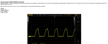
Have you checked to see what is going INTO the modulator with your oscilloscope?
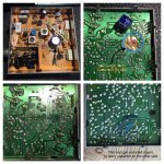
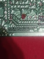
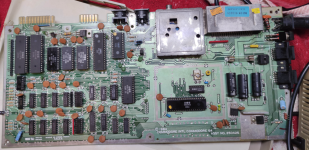
You say you have a C64 - but exactly which version?
Head over to
http://www.zimmers.net/anonftp/pub/cbm/schematics/computers/c64/index.html and identify which exact version you have.
From that you can locate the schematics and then the pinout of the modulator.
For example, on the
http://www.zimmers.net/anonftp/pub/cbm/schematics/computers/c64/250469-rev.B-right-corrected.png schematic you have pin 1 as +5V, the case and pin 3 is 0V and pins 2 and 4 contain the (synchronising and luminance signal) and the (colour signal) respectively.
What do you see on each of these pins relative to 0V?
No voltage on the modulator = no output.
If you see something on pins 2 and 4 it probably indicates that the modulator is not working.
If you see nothing on either pins 2 or 4, you have to work your way back to the VIC chip.
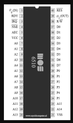
You stated previously that you didn't see the correct waveform on U31 pin 10. But you don't appear to have chased that inconsistency down. If you find a problem, you have to investigate it further... What is the part number actually marked on U31? This part potentially differs on different revisions of the C64 PCB - so pin 10 of U31 may (or may not) have something on it...
You have to make sure all the time that the documentation you find applies to your particular machine.
This document:
http://www.zimmers.net/anonftp/pub/...-C64C_Service_Manual_314001-03_(1992_Mar).pdf describes a number of different C64 variants.
Dave
 ...
...