daver2
10k Member
They look fine.
I am not sure why your frequency meter is not stable. The oscilloscope trace is rock solid though. You may need to read the manual to identify how the internal frequency meter works and whether there is any specific set-up required for it (e.g. oscilloscope Y position or triggering requirements).
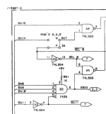
I will post some more points for you to check tomorrow - but (to start you off) there is a small piece of logic in the upper left-hand corner of schematic number 1 providing the direction signals for the octal databus buffers. Where you see a buffered address line identified (BAn) can you check the pin of the associated IC to make sure that the frequency is as expected.
Dave
I am not sure why your frequency meter is not stable. The oscilloscope trace is rock solid though. You may need to read the manual to identify how the internal frequency meter works and whether there is any specific set-up required for it (e.g. oscilloscope Y position or triggering requirements).
I will post some more points for you to check tomorrow - but (to start you off) there is a small piece of logic in the upper left-hand corner of schematic number 1 providing the direction signals for the octal databus buffers. Where you see a buffered address line identified (BAn) can you check the pin of the associated IC to make sure that the frequency is as expected.
Dave