• Please review our updated Terms and Rules here

Cbm dual drive 3040 disk - two red lights

If you remove the wire/resistor that you applied to the LM2917 FIRST and then try it to see if the motor now runs.

If not, we have to rethink why and go back to measuring the voltages on the LM2917 pins again.

If the motor does run, then you can remove the previous link that we applied near to the resistor. The motor should not then run.

Dave
Yes motor run, when i turn on the drive!
 
Excellent my friend!

>>> If the motor does run, then you can remove the previous link that we applied near to the resistor. The motor should not then run.

If you remove this link now, the motor shouldn't run and the drives will be back as they were before we started messing about with them.

We can then try and drive them via the PET and the IEEE4888 port.

All we SHOULD have fixed now though is the motor circuitry. We haven't done anything about the stepper motor(s) yet. That is the next job! So, no getting desperate that the drive doesn't read and write disks!

Incidentally, now that you have replaced the motor speed controller chip, we may have to adjust the speed correctly - but we will do that later.

Dave
 
Last edited:
Incidentally, now that you have replaced the motor speed controller chip, we may have to adjust the speed correctly - but we will do that later.

Dave
Desperado is doing well.

Probably I would think that because of the tight closed loop gain feedback loop (and with the OP amps otherwise having very high open loop gain) replacing the IC would unlikely alter the set speed very much at all......unless say the speed control preset has been tweaked during the repair. So it would still pay to check the speed.
 
Excellent my friend!

>>> If the motor does run, then you can remove the previous link that we applied near to the resistor. The motor should not then run.

If you remove this link now, the motor shouldn't run and the drives will be back as they were before we started messing about with them.

We can then try and drive them via the PET and the IEEE4888 port.

All we SHOULD have fixed now though is the motor circuitry. We haven't done anything about the stepper motor(s) yet. That is the next job! So, no getting desperate that the drive doesn't read and write disks!

Incidentally, now that you have replaced the motor speed controller chip, we may have to adjust the speed correctly - but we will do that later.

Dave
Dave ok, i removed the wire near resistor and now, when i turn on the drive, the motor doesn't run !
So i connected dual drive to Pet....now what can i do to test both drives please?
Thanks!
 
I am just doing my expenses at the moment, so give me a short while.

Previously, I gave you the PET commands to format/initialise the disk drives didn't I? Can you go and find them in the previous posts...

If you try the command for drive 0 (right-hand drive) the drive select light should illuminate AND the motor should run. This was the behaviour before - so it should work the same now.

If that is OK, reset the PET and disk drive (power off, wait, power on) and then try the command I gave you for drive 1 (left hand drive). If we have got the command correct (!) the the left hand drive select light should illuminate AND the motor should now run. It didn't do this before...

Dave
 
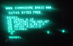
Enter the following sequence of commands into the PET:

10 OPEN 1,8,15
20 PRINT #1,"N0:DER,42"
30 CLOSE 1

Measure UM3 pin 15 (motor on signal for drive 0) and RUN the above program. The pin should change state, the LED on drive 0 should illuminate and the motor should run?

I hope that the drive stops eventually and the LED goes out? Does the PET return to READY?

If so, change line 20 to:

20 PRINT #1,"N1:DER,42"
Ok Dave, now both drives work with these sequence!
 
You fixed the motor drive controller! Well done!

It also seems to me that the IEEE488 port 'probably' works OK. If it didn't, these commands probably wouldn't have worked...

The string is sent down the IEEE488 bus to the disk drive and is processed within the disk drive electronics.

So, did the PET return to the READY prompt after running the program and did you observe any stepper motor action or not?

How long (in seconds) from RUNing the program to returning to the READY prompt did it take?

Dave
 
So, did the PET return to the READY prompt after running the program and did you observe any stepper motor action or not?
I can hear drive spinning and a noise like "ta-ta-ta-ta-ta-ta" for 2 seconds...
How long (in seconds) from RUNing the program to returning to the READY prompt did it take?
10 seconds....
 
>>> I can hear drive spinning and a noise like "ta-ta-ta-ta-ta-ta" for 2 seconds...

I suspect what you can hear is the stepper motor driving the head...

Use the above program for drive 0.

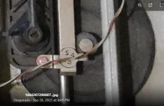
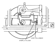
Look at the top of the drive and see if you can find the black disk with a 'snail' cut in it. See the two photographs below. One is from the Shugart manual and the other from one of the photographs you took:

1665758405351.png

1665758561767.png

When you run the program, you may be able to see this black disk with the snail cut-out rotating (slightly).

If so, this indicates that the stepper motor is actually working (on the right-hand drive at least).

You should be able to hear (and - hopefully) see the other drive for the same thing.

If you are unsure, post some more photographs and I will see if I can point you to it further...

Dave
 
>>> I can hear drive spinning and a noise like "ta-ta-ta-ta-ta-ta" for 2 seconds...

I suspect what you can hear is the stepper motor driving the head...

Use the above program for drive 0.

Look at the top of the drive and see if you can find the black disk with a 'snail' cut in it. See the two photographs below. One is from the Shugart manual and the other from one of the photographs you took:

View attachment 1247285

View attachment 1247286

When you run the program, you may be able to see this black disk with the snail cut-out rotating (slightly).

If so, this indicates that the stepper motor is actually working (on the right-hand drive at least).

You should be able to hear (and - hopefully) see the other drive for the same thing.

If you are unsure, post some more photographs and I will see if I can point you to it further...

Dave
I have seen the disk move backwards in both drives. But first I had to rotate the disc slightly by hand and when I ran the program, the disc came back.
unfortunately I couldn't format any disks :(
 
So, that probably means that the stepper motors are working on each of the disk drives!

As there is no "Track 0" sensor switch on these drives, the assumption is that the head can be anywhere. So what happens is that the drive electronics just steps the head out by more tracks than there is on the disk. As a result, the head support just bumps up against the end stops. This is rubbish - but the lack of the switches makes the whole thing much cheaper to manufacture.

Ok, so if the drive motors and stepper motors now work - I have to have a think as to where we go next.

We are getting there though. Good work all round I think.

Dave
 
Can you modify my little program to the following and RUN it please:

10 OPEN 1,8,15
20 PRINT #1,"N0:DER,42"
30 INPUT #1,A,B$,C,D
40 PRINT A,B$,C,D
50 CLOSE 1

Where: A is the error code, B$ is the error text, C is the track number and D is the sector number.

Let's see what this gives us.

Dave
 
Can you modify my little program to the following and RUN it please:

10 OPEN 1,8,15
20 PRINT #1,"N0:DER,42"
30 INPUT #1,A,B$,C,D
40 PRINT A,B$,C,D
50 CLOSE 1

Where: A is the error code, B$ is the error text, C is the track number and D is the sector number.

Let's see what this gives us.

Dave
I have three times "0" Dave..
 

Attachments

  • Schermata 2022-10-15 alle 10.44.20.png
    Schermata 2022-10-15 alle 10.44.20.png
    703.8 KB · Views: 6
One of three possibilities:

1. The formatting worked (unlikely).

2. The INPUT statement didn't work as I expected it to (0 and an empty string are the default values for uninitialised BASIC variables).

3. The disk drive terminated the format early without producing a meaningful error message.

I will come up with a few tests for you after lunch to see (a) whether the stepper motor is really being operated and (b) whether the disk drive electronics is trying to actually write anything at all to the disk.

Dave
 
Right, back to your PET disk drive...

Can I get you to measure a number of signals (using your logic probe powered from +5V).

You need to use my little program from post #813. We will only test drive 0 (right hand drive) to start with. Some (most...) of the signals are common to both drives.

BEFORE you RUN the program, check the logic level of the signals and post the results. Then RUN the program (whilst you have the logic probe connected to the pin of interest) and look for the result we should be seeing.

First let's have a look at the stepper motor drive signals on the analogue board. These are the TTL signals feeding the high-power transistor logic. We can check the logic signals with the logic probe and (if necessary) check the 12V signals going to the stepper motor windings later on with the oscilloscope. But let's not worry about the oscilloscope at this stage...

The first test is on the output of UC1 pin 1 of the analogue board. Post back the initial logic level (before running the program). Make sure you observe some PULSE activity when you RUN my little program. Post back the logic level AFTER the program terminates.

Repeat the above with UC1 pin 13.

If you want to, you can repeat the above tests with UC1 pin 5 and UC1 pin 9 for drive 1 (by changing line 20 of my program to N1 instead of N0).

Do this test and (if all looks good) we will move on to look at the other digital signals (HD SEL 0m DATA OUT, WRITE ENABLE and READ INHIBIT) in the next post.

I forgot to ask, when you run the program, does the centre LED (on the front panel) change state at all?

Dave
 
Before running program:
UC1 PIN 1: HIGH
UC1 PIN 13: HIGH

After running:

UC1 PIN 1: HIGH
UC1 PIN 13: HIGH
Make sure you observe some PULSE activity when you RUN my little program.
When i run program, the HIGH signal on logic probe pulse for 1 second...
 
That's all good. So the logic is trying to drive the stepper motor (but we suspected that to be the case anyhow - but now we have proven it). Not the transistor logic though (we'll do that later).

Right, to the other signals now (again, using your logic probe):

A similar procedure - measure the static logic level of the signal. Observe for any PULSE activity when you RUN the program and then measure the static logic level at the end of the program.

UJ6 pin 2 - HD SEL 0.
UL2 pin 6 - DATA OUT.
UH6 pin 9 - WRITE ENABLE.
UL2 pin 8 - READ INHIBIT.

Let's see if we any sign of it attempting to write anything to the physical disk. Again, note (and report) any activity on the centre RED LED on the front of the drive please.

Dave
 
Dave, JUST FOR CLARITY.... i checked signals on UC1 (74ls04N) on drive's board...ok?
 
Last edited:
Sorry, yes, the main digital logic board.

The reason I asked you to check the stepper signals on the analogue board is that they originate from the device that is covered by your little emulator board. I remembered this time!

Dave
 
Back
Top